
Case
Particulars
Stations, diameters, bearings, propeller, engine and the hull deflections supplied. A checksum of that geometry is carried with every result set derived from it.
Lead practice
An engineering analysis of the complete propulsion shaft line, from the main engine through the shafting and its bearings to the propeller, assessed as one system. It is used to set the shaft alignment of a new or repaired line, to match the engine to the propeller, and to find the cause of high bearing temperature, abnormal wear-down or vibration in service. The method rests on a book-length technical treatment of the same machine, summarised below, and its results can be compared against measurement on the vessel.
The analyses in detail
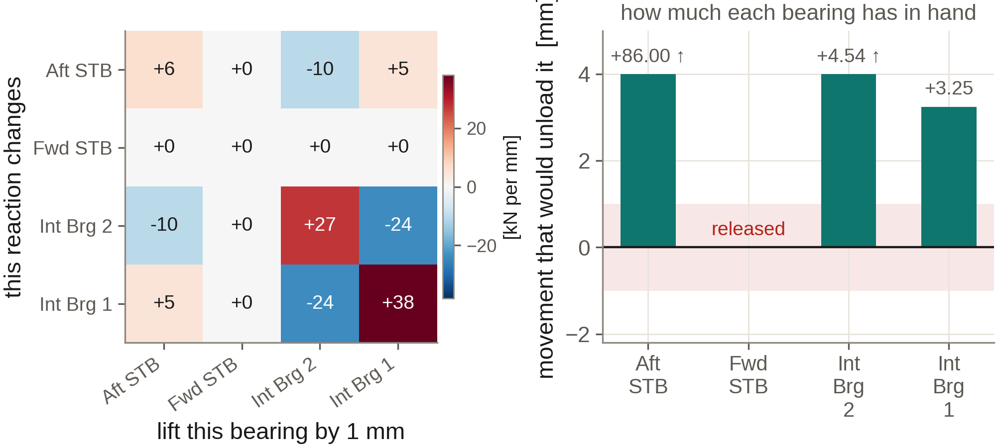
Bearing reactions, slopes, lift-off and influence coefficients for the hot and cold conditions, with chock heights or offsets for installation.
Natural frequencies, order crossings, shaft stress against class limits and barred speed ranges, on a mass-elastic model of the complete train.
Axial modes against blade-rate excitation and lateral whirling with bearing coefficients from the film solution, in one rotor model.
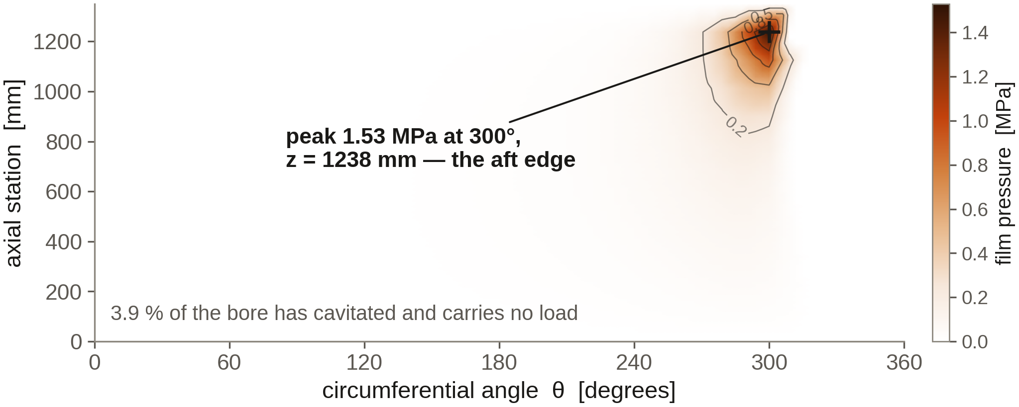
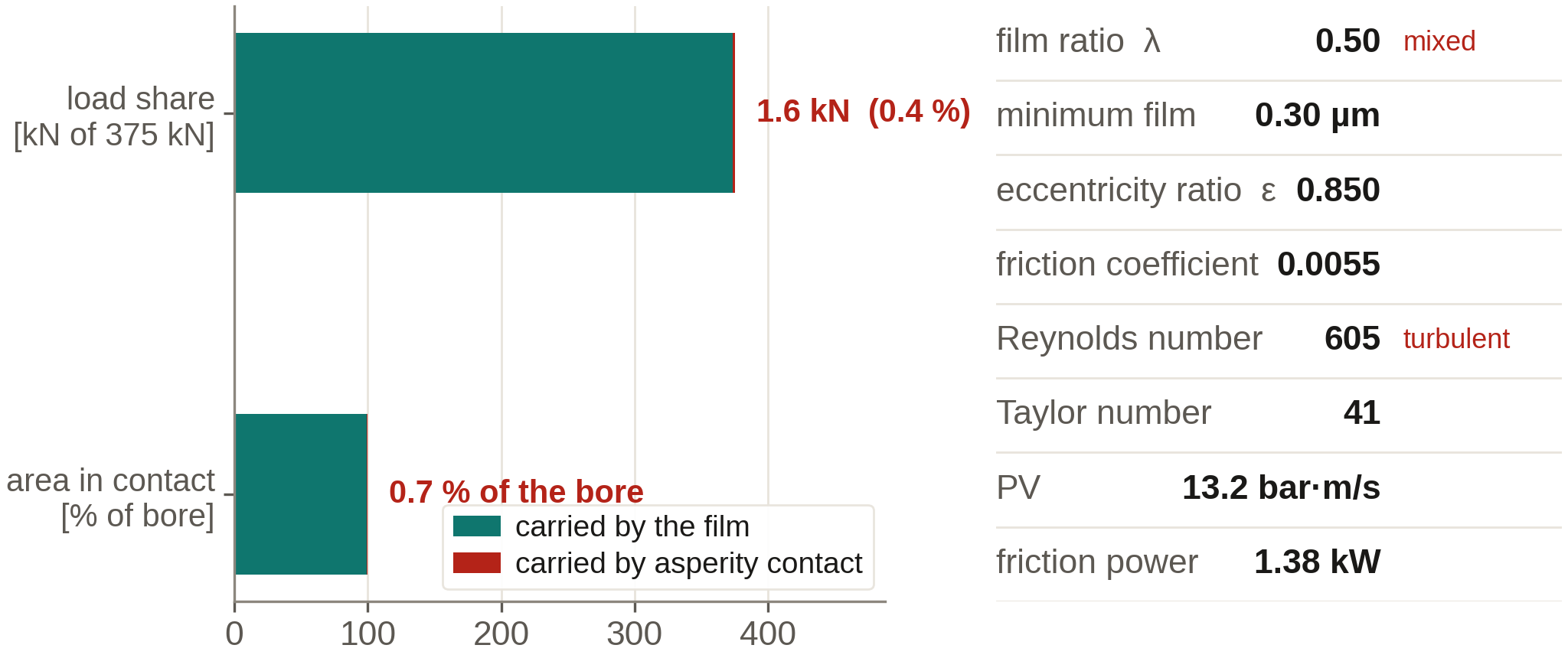
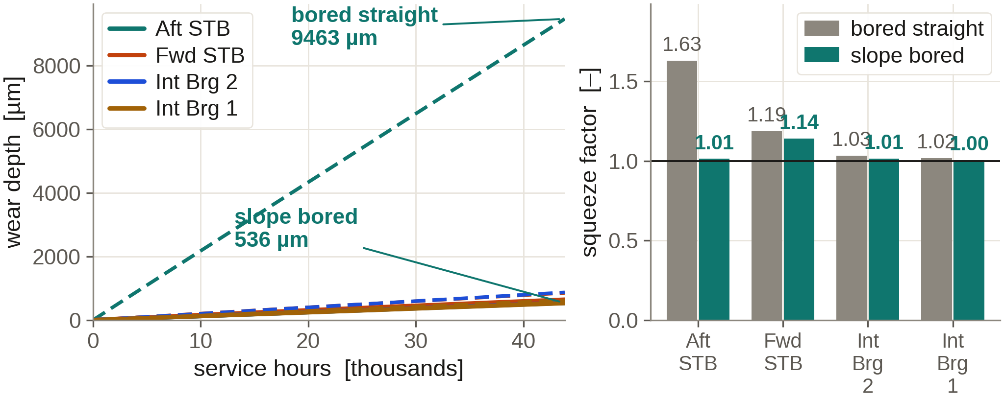
Film thickness, edge loading, lift-off speed and comparative wear for water- and oil-lubricated stern tube bearings, straight or slope bored.
Where the propeller absorbs the engine power across the operating range, with light-running, fouling and weather margins set out.
Blade geometry, offset tables and section drawings for the manufacturer, with mass and inertia for the shafting calculations.
Shaft alignment is sometimes treated as a matter of record: a set of offsets, a bearing pressure limit and a signed acceptance sheet. The behaviour of the installed line does not support that treatment.
A hull deflects as tanks are filled and as draught and trim change. The propeller applies a steady thrust together with a fluctuating force and moment at blade rate. A polymer stern tube bearing absorbs water, swells, and wears where the service is sediment-laden. An arrangement that is within tolerance in dry dock can edge-load the aft end of the stern tube on the first laden voyage. The consequence appears later as elevated bearing temperature, discoloured oil, abnormal wear-down or a wiped surface, and the cause is commonly a relative slope that was never established on any drawing.
The analysis therefore proceeds from quantities that can be calculated and independently checked: the load carried by each support, the hull deflection field acting on the line, the film that seawater will sustain at a specific bearing pressure of a few tenths of a megapascal, the effect of edge loading over a long stern tube bush, and the relation between a measured jacking curve and the calculated influence matrix.
Thermal growth of the engine and its seating displaces the line between cold and hot conditions. Both conditions are calculated, and both are reported.
Technical basis
The treatise runs from the mathematical foundations to the problems that remain open. A client study does not reprint it. A result is used in a study only because it has been derived at one of the levels below, and the report is able to identify which.
| Level | What it provides to the analysis |
|---|---|
| Foundations | Coordinate systems, finite rotation, elasticity, energy methods, and the direct stiffness formulation used by the beam and rotor models. Later chapters derive from these rather than assume them. |
| The plant | Anatomy of the shafting, shaft and bearing materials, seawater as both lubricant and environment, the stern tube boundary, and bearing span and layout practice. |
| Beam analysis | The shaft as a continuous beam on elastic supports. Combined bending, torsional and axial stress; minimum diameters to IACS UR M68 and class rules; fatigue assessment and barred speed range. |
| Vessel loads | Hull deflection, propeller weight, buoyancy and immersion, thermal growth of the engine and seatings, propeller hydrodynamics and cavitation, and the match between a two-stroke engine and the propeller law. |
| Alignment | Acceptance criteria, influence coefficients, the jacking test, and the installation sequence that converts calculated offsets into chock heights. |
| Lubrication | Clearance and film formation in a water-lubricated stern tube, elastic deformation of soft bearing material, mixed lubrication, thermal effects within the film, and the wear that follows from them. |
| Dynamics | Rotor equations including gyroscopic terms, Campbell diagrams, stability, torsional, axial and lateral vibration, and the coupling between alignment and each of them. |
| Practice | Sea trials, diagnostic measurement, comparison of the model against the vessel, and a stated account of what the model is not able to resolve. |
Computed output
These figures are output from the in-house shaft-line software applied to a reference vessel: 39.2 m shafting, 18 660 kW at 91 r/min, driving a 7.6 m five-bladed propeller. A study of your vessel uses its own geometry; the form of the results is the same.
Deliverables
Application
The analysis is used to confirm that the propeller lets the engine reach its rated power, to set chock heights, to decide whether a stern tube should be slope bored, to establish which bearing will reach its limit first, and to interpret a vibration or temperature complaint against the alignment that produced it.
The calculation is prepared so that a yard can follow and reproduce it. It is lodged by the party the classification society expects to sign, with a report written to support that party, and we support the review itself: the society’s questions on the calculation are answered by us, with further cases run where they are asked for, until the review is closed.
How a study is built
Alignment, lubrication and vibration are frequently produced as three separate calculations that have diverged by the time they reach the superintendent. A single vessel case holds the geometry and the machinery data, and every subsequent result is read from that case rather than re-entered.
Case
Stations, diameters, bearings, propeller, engine and the hull deflections supplied. A checksum of that geometry is carried with every result set derived from it.
Handover
The alignment writes, once, the load and the relative slope at each bearing. The lubrication and rotor models read those values; they do not restate them.
Return
Dynamic bearing load and shaft orbit are returned to the lubrication model where the running condition differs from the static one. Wear is projected from the resulting duty.
Account
Inputs that are measurements and inputs that are assumptions are labelled distinctly throughout. A gap in the data is reported as such.
Technical basis
The in-house shaft-line software rests on a technical treatise on marine propulsion shafting. The mathematics is established first: the stiffness formulation, the energy principle and the gyroscopic moment are derived before a bearing reaction is relied upon.
The treatment then follows the plant itself: layout and bearing span; the beam on elastic supports; shaft strength and fatigue; hull deflection and propeller loads; the engine and the propeller law; influence coefficients and the jacking test; the seawater film and mixed lubrication; torsional, axial and lateral vibration and the interaction of alignment with each; and sea trials, where the computational model is compared against the vessel rather than adjusted until the residual disappears.
That body of work is the technical foundation of the company and the reason propulsion shafting is the lead service. Machinery design and customised analysis are conducted on the same basis: a defined free body, stated assumptions, and a calculation that can be repeated by another engineer.
Discipline on a live engagement
Comparison against measured data is reported as a discrepancy. The model is not adjusted until a jacking curve is reproduced. Where an input is revised, the revision, its justification and its effect on the result are recorded in the report.
Collaboration
Certain shaft-line problems are not yet reducible to a deliverable. Polymer contact behaviour once the film collapses, hull compliance expressed as a measured matrix, and a wear rate for a bearing that has never been surveyed in dry dock are research questions. Within a study they are identified as such, together with the measurement or survey that would settle them, rather than answered by default.
Advik Protofab works with engineers, owners, yards and academic partners on those questions where the work produces evidence on which a vessel can act. A collaboration is expected to have a vessel, a measurement, or a calculation with an independent check attached to it.
Input data