
Services · Propulsion shafting · Shaft alignment analysis
Propulsion shaft alignment analysis
A shaft alignment calculation that sets every bearing at the height the loaded line needs, from the aft stern tube bearing to the last engine main bearing. It covers the cold and hot conditions and the draughts the vessel works at, gives the bearing offsets or chock heights for the yard, and checks the result against jacking and gap-and-sag measurement. It is the same calculation for a newbuilding, a repair, a conversion or a vessel already showing high bearing temperature or wear-down.
What the calculation establishes
The shaft line is treated as a continuous beam on elastic supports. Each bearing is a support with its own offset, stiffness and length, and the stern tube bearings are modelled over their full length so that contact can move along the bush. The propeller enters as a concentrated mass with its buoyancy at the stated immersion, and the engine crankshaft is carried into the model so that the main bearing loads are calculated, not assumed.
For each condition the study reports the reaction at every bearing, the relative slope between the shaft and the bush at the stern tube, the bending moment and stress along the line, and the margin each bearing holds before it unloads. Where the shaft lifts clear of a bearing, the calculation releases that support and solves again, and re-engages it if the shaft settles back. That step matters: a calculation that keeps iterating a fixed influence matrix across a lift-off reports loads that look reasonable and are wrong.
The conditions that are calculated
- Cold, in dry dock and afloat. The installation condition, at the immersion the propeller has when the bearings are set.
- Hot, at service temperature. The engine bed and the crankcase grow, and the engine bearings rise with them.
- Ballast and laden. Hull deflection from the design office or class file is applied to the bearing offsets, condition by condition.
- Propeller eccentric thrust. Where the wake makes it significant, the bending moment it applies at the propeller is carried as a further load case.
What you receive
- Bearing reactions, slopes and stress for every condition, tabulated and plotted.
- The influence coefficient matrix: the change in every bearing reaction per millimetre of offset at each adjustable bearing, which is the tool a yard uses to correct an installation.
- Bearing offsets for installation, or chock heights where the scope extends to the engine seating.
- The gap and sag values to set at each flange, and the jacking loads to expect at each accessible bearing.
- A check of every condition against the acceptance criteria of the classification society and the engine designer.
- A report written for the party that submits it to class, with our support through the review until it is closed.
Every input is labelled as measured, supplied or assumed. Where an assumption governs a result, the report says so and states the measurement that would settle it.
Worked example
The reference line, calculated
The in-house shaft-line software applied to a reference installation: 39.2 m of shafting with two stern tube bearings, two intermediate bearings and eight engine main bearings, 18 660 kW at 91 r/min, driving a 7.6 m five-bladed propeller.
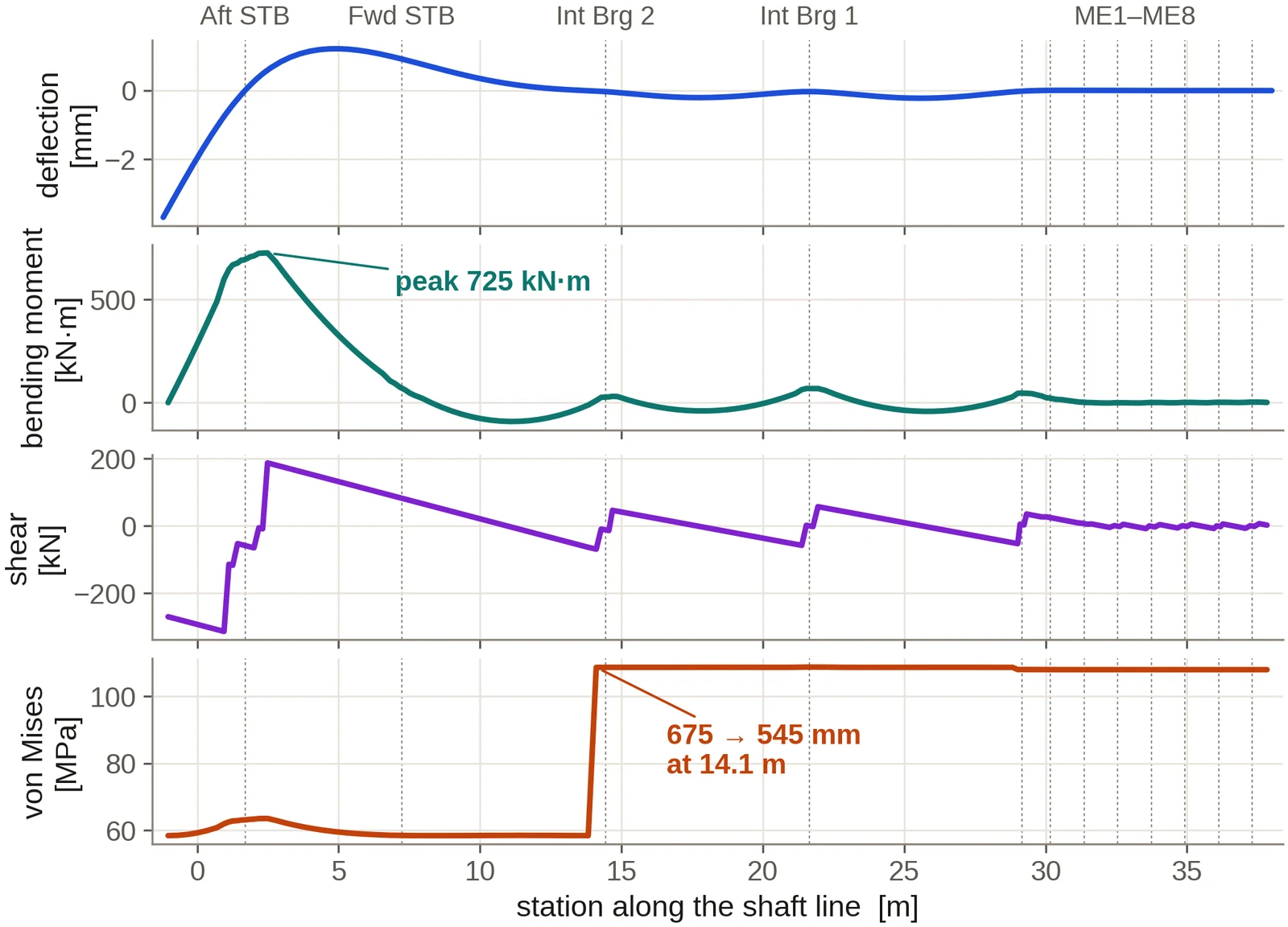
Checked against a shipyard's own calculation
The alignment model has been run against a complete, class-approved yard calculation for a large crude carrier: nine bearings, six load cases hot and cold, and the yard's full influence matrix. The matrix is symmetric to the last printed digit, as reciprocity requires, which confirms both the source and its transcription. Between the hot and cold cases, where every bearing stays loaded, the change in reaction at the stern tube and intermediate bearings is reproduced within 22 N, and at the engine bearings within 2.2 %, which is the rounding of the printed coefficients.
Why lift-off is handled explicitly
The same yard data shows where superposition stops working. Between two cases that differ only in offsets, one of which has a bearing lifted clear, a fixed influence matrix is out by up to 74 kN and adds 33 kN of load that is not there. The in-house solver releases a bearing found in tension and re-engages one the shaft settles back onto, so every reported reaction belongs to the contact state the line is actually in.
In service
When the alignment is the suspect
High aft stern tube bearing temperature, a wiped bearing, wear-down growing faster than expected, discoloured oil or a vibration complaint at a particular draught are often traced to alignment. The study starts from what the machinery is doing: bearing temperatures and wear-down records, any jacking or gap-and-sag readings, and the loading conditions in which the complaint appears. The model is then built to explain those observations, and the correction is stated as offsets the yard can set.
Input data
What the study needs
- The shafting arrangement drawing, with bearing positions, lengths and clearances.
- Propeller mass, diameter and immersion, and the engine designer's crankshaft and main bearing data.
- Hull deflections where the design office or class file holds them.
- Any jacking, gap and sag, laser or bearing temperature records. A single measured point sharpens the result.
Questions from owners and yards
Frequently asked
Is the calculation accepted by classification societies?
The report follows the content the societies ask for in an alignment submission: the model, the conditions, reactions, slopes, stresses and the influence matrix, with the criteria each result is checked against. It is submitted by the party class expects to sign, usually the yard, and we answer the society's questions and run further cases until the review is closed.
Can you work from an older vessel's drawings alone?
Yes. A shafting arrangement drawing and the propeller and engine particulars are enough to build the model. Where hull deflection data has not survived, the hull conditions are bounded from the vessel's type and size and the result is stated for that range, so the alignment chosen holds across it.
Do you provide jacking-test support?
The study gives the expected jacking load at each accessible bearing and the correction factor to apply to the measured value. Measured jacking curves sent to us are reduced to bearing reactions and compared with the model, and any difference is reported and explained.
Is a single stern tube bearing arrangement covered?
Yes. A single stern tube bearing makes the line more sensitive to propeller eccentric thrust and to the relative slope at the bush, and the study gives both particular attention, including whether slope boring is advisable.
How long does a study take?
The written scope states the delivery date before any work begins, and it is held to. A conventional line with complete data is one of the shorter studies we run; an in-service investigation is scheduled around the records and any measurement still to be taken.
Commissioning
Start with the drawings you hold
Send the shafting arrangement drawing and whatever machinery data is to hand. An initial technical response follows within two working days, then a written scope and proposal: the conditions to be calculated, the data still needed, the deliverables, the fee and the schedule. A non-disclosure agreement can be put in place before any drawing is exchanged. The calculation is then carried through to a report a yard, a superintendent or a classification society can follow and reproduce, and questions raised on it are answered by us until the review is closed.
Related analyses
Torsional vibration analysis
Natural frequencies, order crossings, shaft stress against class limits and barred speed ranges, on a mass-elastic model of the complete train.
Axial and whirling vibration
Axial modes against blade-rate excitation and lateral whirling with bearing coefficients from the film solution, in one rotor model.
Stern tube bearing analysis
Film thickness, edge loading, lift-off speed and comparative wear for water- and oil-lubricated stern tube bearings, straight or slope bored.
Propeller and engine matching
Where the propeller absorbs the engine power across the operating range, with light-running, fouling and weather margins set out.
Propeller geometry and offsets
Blade geometry, offset tables and section drawings for the manufacturer, with mass and inertia for the shafting calculations.
3D hull, CFD and wake
The hull rebuilt from your drawings, with viscous resistance and the wake the propeller works in.