
Services · Propulsion shafting · Torsional vibration analysis
Torsional vibration analysis of the propulsion train
A torsional vibration calculation of the complete propulsion train, from the engine's damper and crank throws through the flywheel and shafting to the propeller. It gives the natural frequencies, the speeds at which engine and propeller orders excite them, the alternating stress in every shaft section against the classification society's limits, and the barred speed range the bridge will observe. It serves a newbuilding, a repowering, a change of propeller or damper, and the investigation of a vibration or a cracked shaft in service.
What the calculation covers
- Natural frequencies and mode shapes of the free train, with the node positions that show where the shafting is worked hardest.
- Excitation from the engine's gas and inertia harmonics, taken order by order with the firing sequence, and from the propeller at blade rate and its multiples.
- Forced response across the speed range: vibratory torque, twist and alternating shear stress in each shaft section and in the crankshaft.
- Assessment against class limits for continuous running and for passing quickly through a barred range, with the material, diameter and stress concentration of each section.
- The barred speed range, its limits and the margin to the operating speeds.
- Damper and flywheel options: the effect of a viscous or spring damper, or a change of flywheel or tuning wheel, on the critical speeds and stresses.
- Transient events, such as an ice impact on a blade, as a time history of torque and stress along the train.
Why the whole train is modelled
A torsional answer depends on the engine. The crankshaft carries most of the inertia and a large share of the flexibility, and the damper is tuned to the mode it is meant to hold down. A model that keeps the shafting and propeller and reduces the engine to a single block is a different machine, and its frequencies are wrong by more than any margin can absorb.
The in-house shaft-line software therefore builds the torsional train from the engine designer's data, throw by throw, and keeps the lateral alignment rotor for the lateral work it suits. Both are generated from the same vessel case, so the propeller inertia, shaft diameters and bearing positions are entered once.
A torsional calculation is usually required by class for a new installation and after any change to the engine, damper, flexible coupling, shafting or propeller.
Validation
Reproducing a shipyard's own calculation
The torsional model was set against the documented propulsion train of a large crude carrier driven by a low-speed two-stroke engine, for which the shipyard's full mass-elastic calculation is held. Built from the same data, the in-house model reproduces the yard's first natural frequency to better than one per cent, and places the critical speed of the engine's main order inside the yard's barred range. The chart shows what happens when the model is simplified.
Worked example
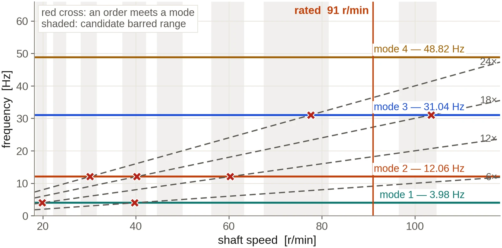
Order crossings on the reference line
The reference installation: a six-cylinder engine of 18 660 kW at 91 r/min driving a 7.6 m five-bladed propeller through 39.2 m of shafting.
Deliverables
What you receive
- The mass-elastic model, tabulated, with the source of every inertia and stiffness.
- Natural frequencies, mode shapes and the interference diagram.
- Vibratory torque and stress against speed for each shaft section, with the class limits drawn in.
- The barred speed range, ready for the engine-room and bridge placards.
- Where a damper, coupling or flywheel is in question, the comparison of the options considered.
- A report written for class submission, and our support through the review.
Input data
What the study needs
- The engine designer's torsional data: inertias and stiffnesses of the crank throws, damper, flywheel and turning wheel, and the harmonic excitation table.
- The shafting arrangement drawing with diameters, lengths and materials.
- Propeller inertia in air, number of blades and diameter. The entrained water is calculated.
- Damper or flexible coupling data sheets, where fitted.
- Any torsional measurement taken on trials or in service.
Questions from owners and yards
Frequently asked
Our barred speed range sits close to a speed we need. What can be done?
The study shows which mode and order set the range and what moves it: a different damper, a tuning wheel or flywheel, a change of shaft diameter or material, or a propeller with a different inertia. Each option is calculated, and its effect on the range and on the stresses is set side by side so the choice can be made on evidence.
We have changed the propeller. Is a new torsional calculation needed?
Usually, yes. The propeller's inertia and its entrained water set the first mode, so a new propeller moves the critical speeds. Class normally asks for the calculation to be revised, and the study gives the updated barred range for the placards.
Do you cover four-stroke engines with gearboxes and flexible couplings?
Yes. Four-stroke engines are assessed with the half-order criticals class asks for. A geared train is referred to one reference speed through the gear ratio, and a flexible coupling is entered with the dynamic stiffness and damping from the maker's data sheet.
Can you investigate a shaft that has cracked?
Yes. The torsional stresses are calculated at the failed section and combined with the bending and axial stresses the alignment and axial calculations give, so the fatigue assessment reflects every load the section carried.
Commissioning
Start with the drawings you hold
Send the shafting arrangement drawing and whatever machinery data is to hand. An initial technical response follows within two working days, then a written scope and proposal: the conditions to be calculated, the data still needed, the deliverables, the fee and the schedule. A non-disclosure agreement can be put in place before any drawing is exchanged. The calculation is then carried through to a report a yard, a superintendent or a classification society can follow and reproduce, and questions raised on it are answered by us until the review is closed.
Related analyses
Shaft alignment analysis
Bearing reactions, slopes, lift-off and influence coefficients for the hot and cold conditions, with chock heights or offsets for installation.
Axial and whirling vibration
Axial modes against blade-rate excitation and lateral whirling with bearing coefficients from the film solution, in one rotor model.
Stern tube bearing analysis
Film thickness, edge loading, lift-off speed and comparative wear for water- and oil-lubricated stern tube bearings, straight or slope bored.
Propeller and engine matching
Where the propeller absorbs the engine power across the operating range, with light-running, fouling and weather margins set out.
Propeller geometry and offsets
Blade geometry, offset tables and section drawings for the manufacturer, with mass and inertia for the shafting calculations.
3D hull, CFD and wake
The hull rebuilt from your drawings, with viscous resistance and the wake the propeller works in.