
Services · Propulsion shafting · Axial and whirling vibration
Axial and whirling vibration of the shaft line
The two vibration checks that complete a shafting assessment alongside torsion. Axial vibration is the shaft line and engine moving fore and aft as a spring and mass, driven by the variation of propeller thrust at blade rate. Whirling is the shaft bending and orbiting inside its bearings. Both are calculated on the same rotor and geometry as the alignment, with bearing stiffness and damping taken from the film the alignment produces.
Axial vibration
On a long-stroke two-stroke engine the crankshaft is axially flexible, and its axial mode couples with torsion through the throws. Propeller thrust varies at blade rate and its multiples, and where one of these orders meets the axial natural frequency the whole line moves fore and aft, loading the thrust bearing, the crankshaft and the engine structure.
The calculation gives the axial natural frequencies with the thrust bearing and seating stiffness, the crankshaft's axial stiffness and the propeller's entrained water, and the forced response against the guidance limit for axial displacement at the crankshaft's free end. Where an axial damper is fitted, the response is calculated with the damper in service and out of action, because the second case sets what the crew must do if it fails.
Why the damper case matters
On the large crude carrier used to validate the model, the yard's coupled axial and torsional calculation shows the axial displacement within the guidance limit with the damper in service. With the damper out of action it exceeds the limit from about one third of rated speed upward, so the ship would have to bar about two thirds of its speed range. That is why the damper's condition is monitored and its failure is treated as a slow-down condition, not a note in the log.
Whirling vibration
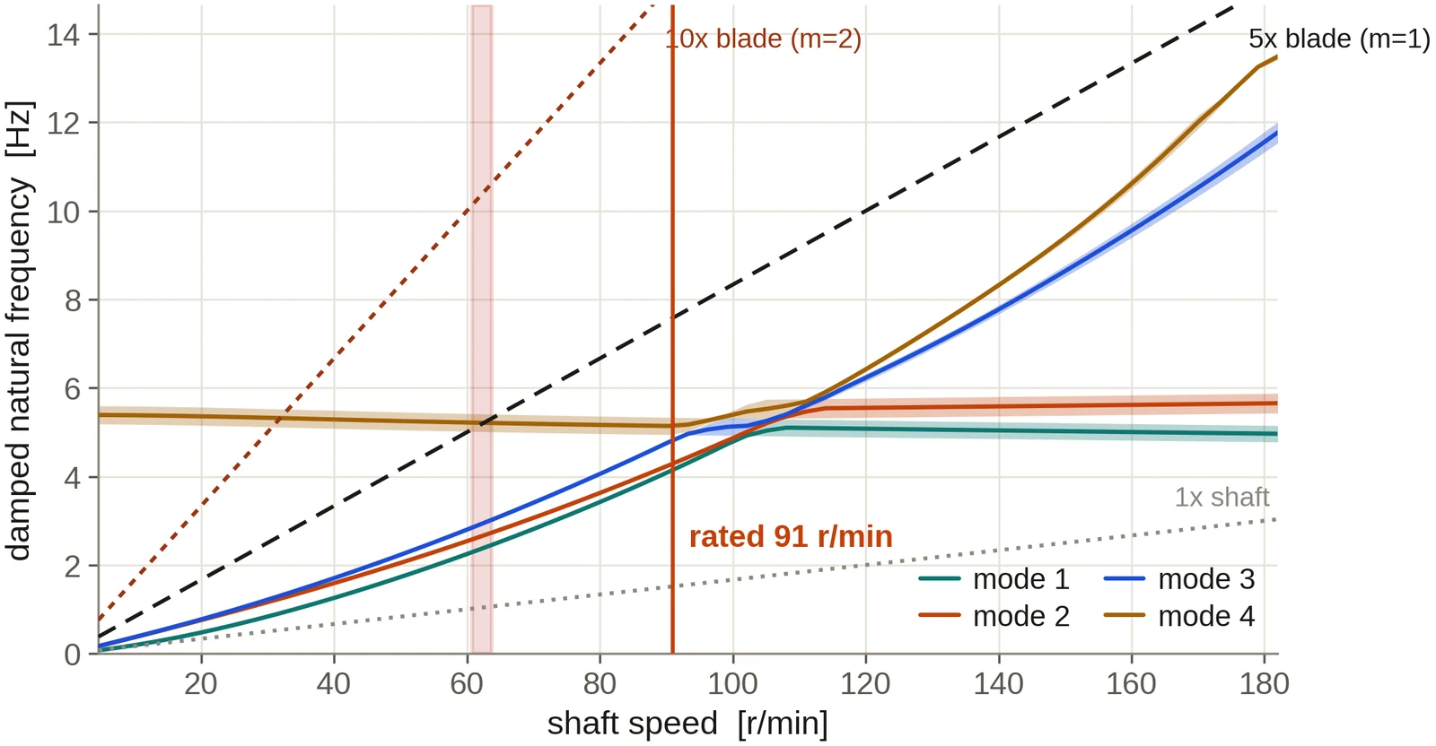
Whirling is the lateral bending of the shaft line as it turns. Its natural frequencies depend on the bearing positions and the propeller overhang, and on the stiffness and damping of the oil or water film in each bearing, which change with load and speed. The propeller's gyroscopic moment splits each mode into a forward and a backward whirl that separate as the shaft speeds up.
The calculation builds the rotor with gyroscopic terms and speed-dependent bearing coefficients taken from the film solution at the load the alignment gives each bearing. It reports the Campbell diagram, the crossings with shaft speed and blade-rate orders, the precessional shape of each mode with its direction of whirl, the damping of each mode and the stability of the rotor across the speed range. The classification societies' guidance on whirling, including the allowance for where along a long stern tube bearing the effective support lies, is applied as a band of frequencies, not a single line.
Worked example
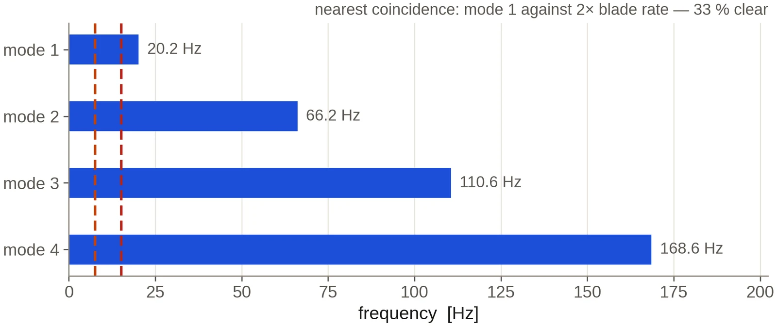
The reference line: axial modes and the whirl band
Results from the in-house shaft-line software for the reference installation: 39.2 m of shafting, 18 660 kW at 91 r/min, and a 7.6 m five-bladed propeller, so blade rate is 7.6 Hz at rated speed.
Deliverables
What you receive
- Axial natural frequencies and forced response, with the damper in service and out of action where one is fitted.
- Thrust bearing load variation and crankshaft free-end displacement against the guidance limits.
- The whirling Campbell diagram with forward and backward modes, the support-point band and the damping of each mode.
- The precessional shape of each mode: where along the line the shaft moves, and which way it whirls.
- Rotor stability across the speed range.
- Any speed range to be avoided, and the measures that would remove it.
Input data
What the study needs
- The shafting arrangement drawing and the alignment calculation, if one exists. If not, the alignment is calculated as part of the study.
- The engine designer's axial data: crankshaft axial stiffness, thrust bearing and seating stiffness, and the axial damper particulars.
- Propeller mass, inertia, diameter and number of blades.
- Bearing dimensions, clearances and lubricant.
Questions from owners and yards
Frequently asked
The thrust bearing shows high temperature or fretting. Can axial vibration be the cause?
It can. The study calculates the thrust variation at the thrust bearing across the speed range and identifies whether an axial resonance falls near the speeds the vessel runs at. If it does, the measures to move it or damp it are set out and calculated.
Is whirling a concern on a conventional merchant ship?
On most lines the first whirling mode is well clear of the operating range, and the calculation confirms that with a stated margin. It needs closer attention with a long propeller overhang, a single stern tube bearing, a widely spaced intermediate bearing, or a soft bearing material whose film stiffness is low.
Are the bearing coefficients taken from a handbook?
No. They are calculated from the film in each bearing at the load and misalignment the alignment gives it, so a change to the alignment is reflected in the vibration result.
Can you compare the results with vibration measured on board?
Yes. Measured axial or lateral vibration from trials or a survey is compared with the calculated response, and any difference is reported and explained in terms of the inputs that would account for it.
Commissioning
Start with the drawings you hold
Send the shafting arrangement drawing and whatever machinery data is to hand. An initial technical response follows within two working days, then a written scope and proposal: the conditions to be calculated, the data still needed, the deliverables, the fee and the schedule. A non-disclosure agreement can be put in place before any drawing is exchanged. The calculation is then carried through to a report a yard, a superintendent or a classification society can follow and reproduce, and questions raised on it are answered by us until the review is closed.
Related analyses
Shaft alignment analysis
Bearing reactions, slopes, lift-off and influence coefficients for the hot and cold conditions, with chock heights or offsets for installation.
Torsional vibration analysis
Natural frequencies, order crossings, shaft stress against class limits and barred speed ranges, on a mass-elastic model of the complete train.
Stern tube bearing analysis
Film thickness, edge loading, lift-off speed and comparative wear for water- and oil-lubricated stern tube bearings, straight or slope bored.
Propeller and engine matching
Where the propeller absorbs the engine power across the operating range, with light-running, fouling and weather margins set out.
Propeller geometry and offsets
Blade geometry, offset tables and section drawings for the manufacturer, with mass and inertia for the shafting calculations.
3D hull, CFD and wake
The hull rebuilt from your drawings, with viscous resistance and the wake the propeller works in.