
01
Main engine
Rated power and speed, the engine load diagram, and thermal growth of the engine and its seating. The engine is matched to the propeller across the operating range, not at one point.
From main engine to hull and propeller
One model of the stern: structure, shaft line, propeller and rudder
Generated with our own software on a container ship's stern. Floors, girders, web frames, longitudinals, collars and end brackets are placed by class rules and shipyard standard details, on the same axis as the stern tube, shafting, propeller and rudder. The main engine is shown as its envelope.

Specialised engineering services · propulsion
We analyse and design the flow around the hull and into the propeller, the propeller itself, the propulsion shaft line, and the machinery and piping systems that serve the ship. Propulsion is our specialisation: the main engine, the shafting, the bearings and the propeller are assessed as one system, from propeller and engine matching to shaft alignment, stern tube bearing wear, and torsional, axial and whirling vibration. Every result is documented so that the yard, the owner and the superintendent can check it.
Systems integration
The engine, the shafting, the bearings and the propeller are specified and supplied by different parties, and most shaft-line problems arise at the interfaces between them. Each component is assessed with the loads and displacements the other three impose on it.
01
Rated power and speed, the engine load diagram, and thermal growth of the engine and its seating. The engine is matched to the propeller across the operating range, not at one point.
02
Strength to IACS UR M68 and class rules, alignment across the hull deflection cases, influence coefficients, and the bearing offsets or chock heights that set the line.
03
Load, relative slope and lubricating film in the stern tube and line bearings, the duty each carries, and which bearing reaches its limit first.
04
Geometry, mass and polar inertia, and the open-water characteristic that fixes where the propeller absorbs the engine’s power. Offsets and section data are prepared for the manufacturer.
Ships in service
Newbuilding, conversion and repair
Premium service 3D hull · CFD · wake
Yards rarely hand over the 3D hull. We rebuild it from the drawings you already hold, check it against your own hydrostatics, and run viscous CFD on it: resistance split into friction and pressure, the wake where your propeller turns, and a speed–power curve calibrated to your trial or model-test data. It is the basis for a performance baseline, for EEXI, EEDI and CII work, and for propeller or energy-saving-device studies.
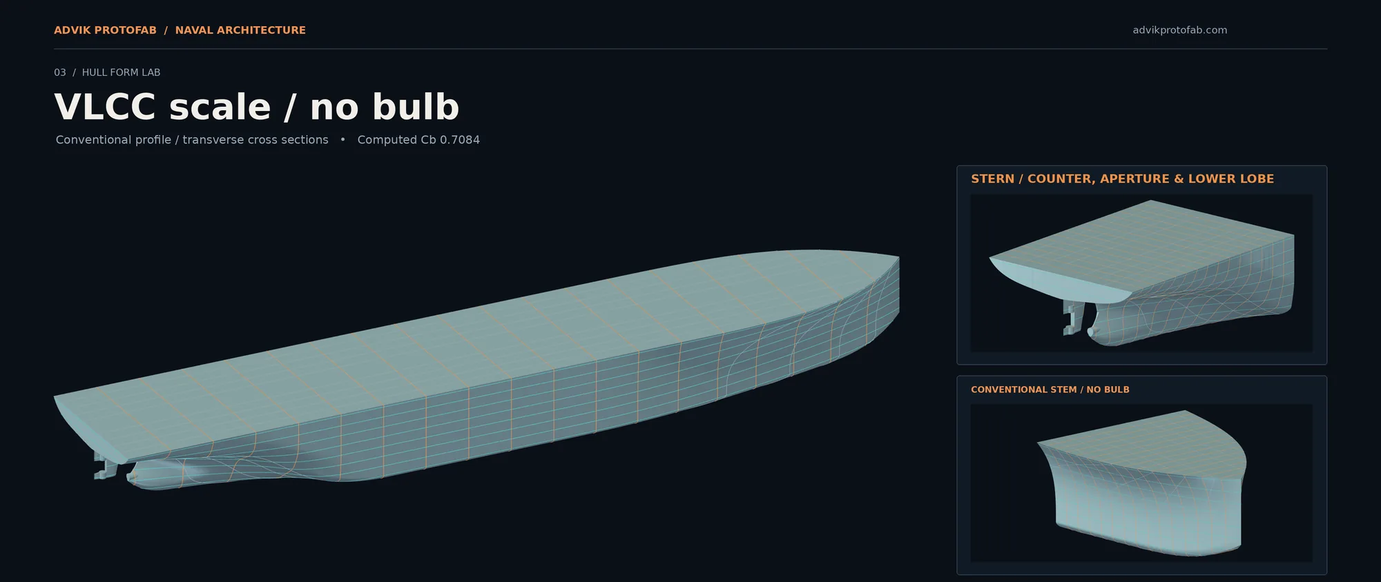
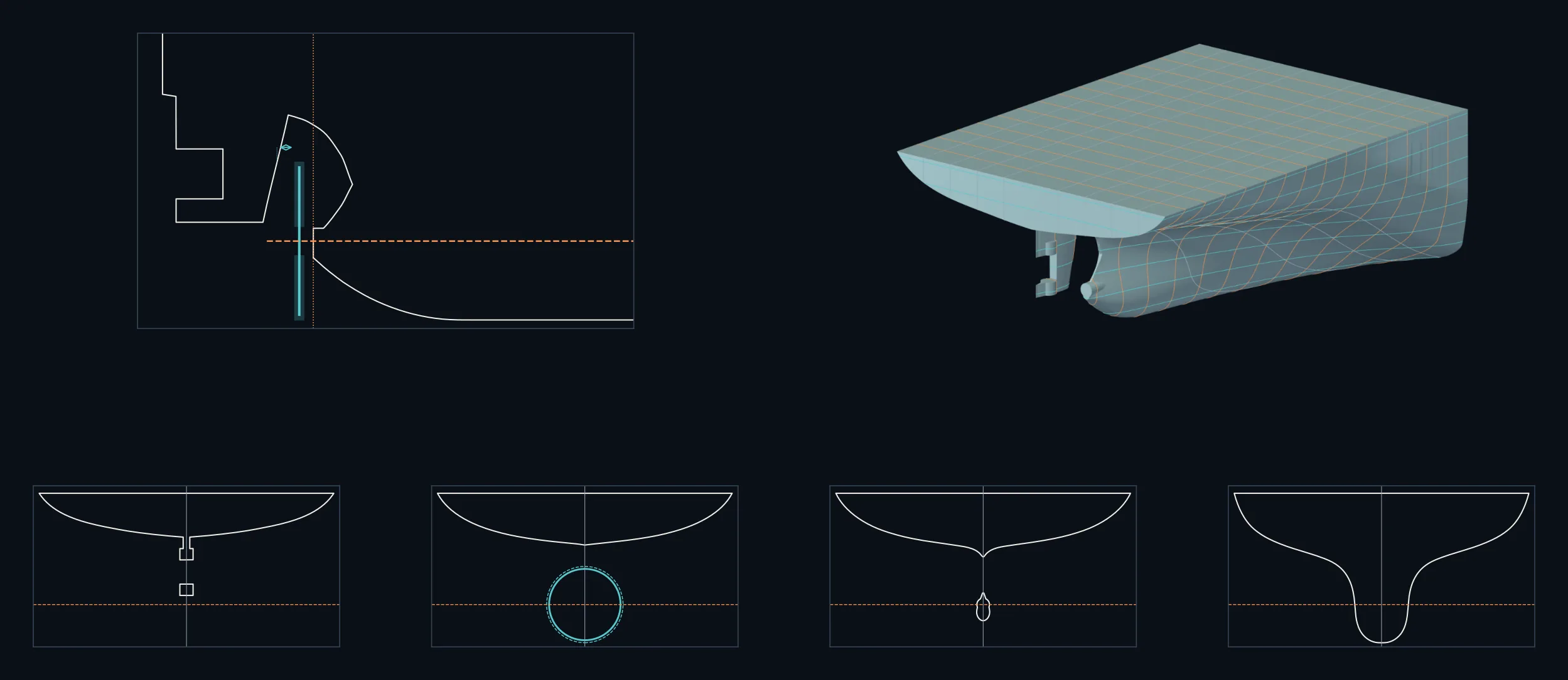
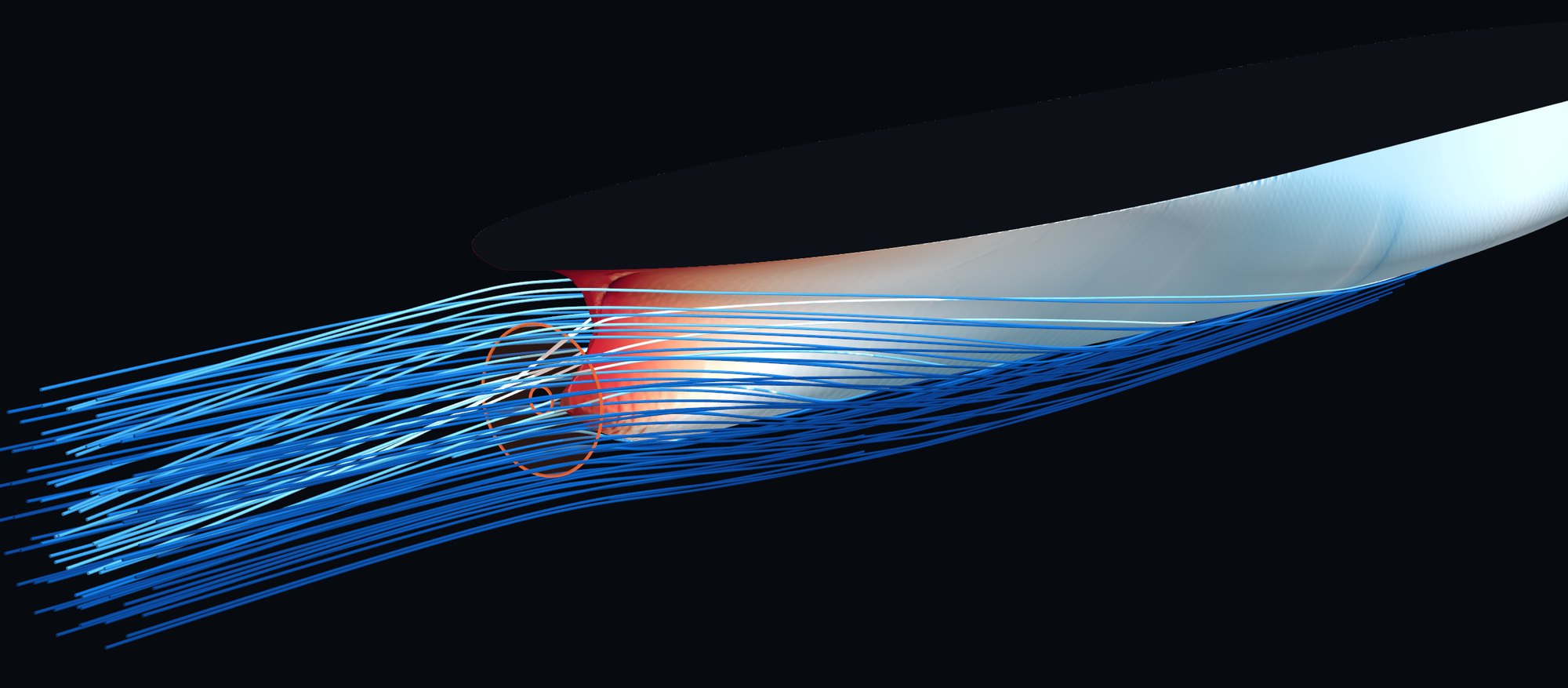
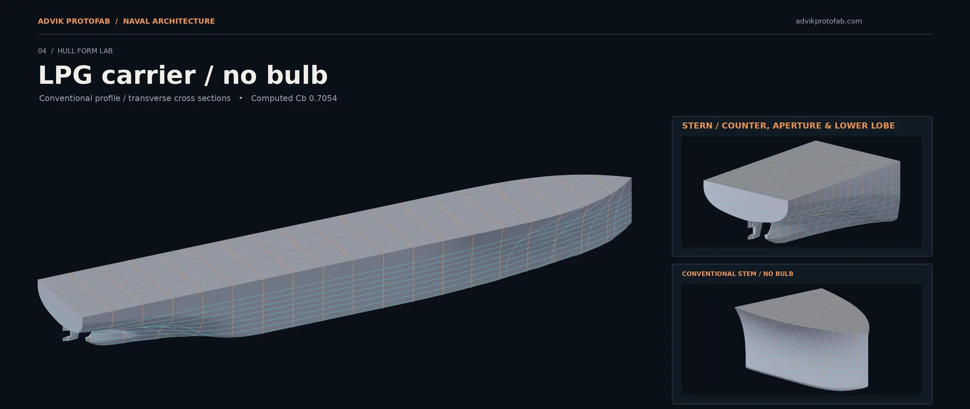
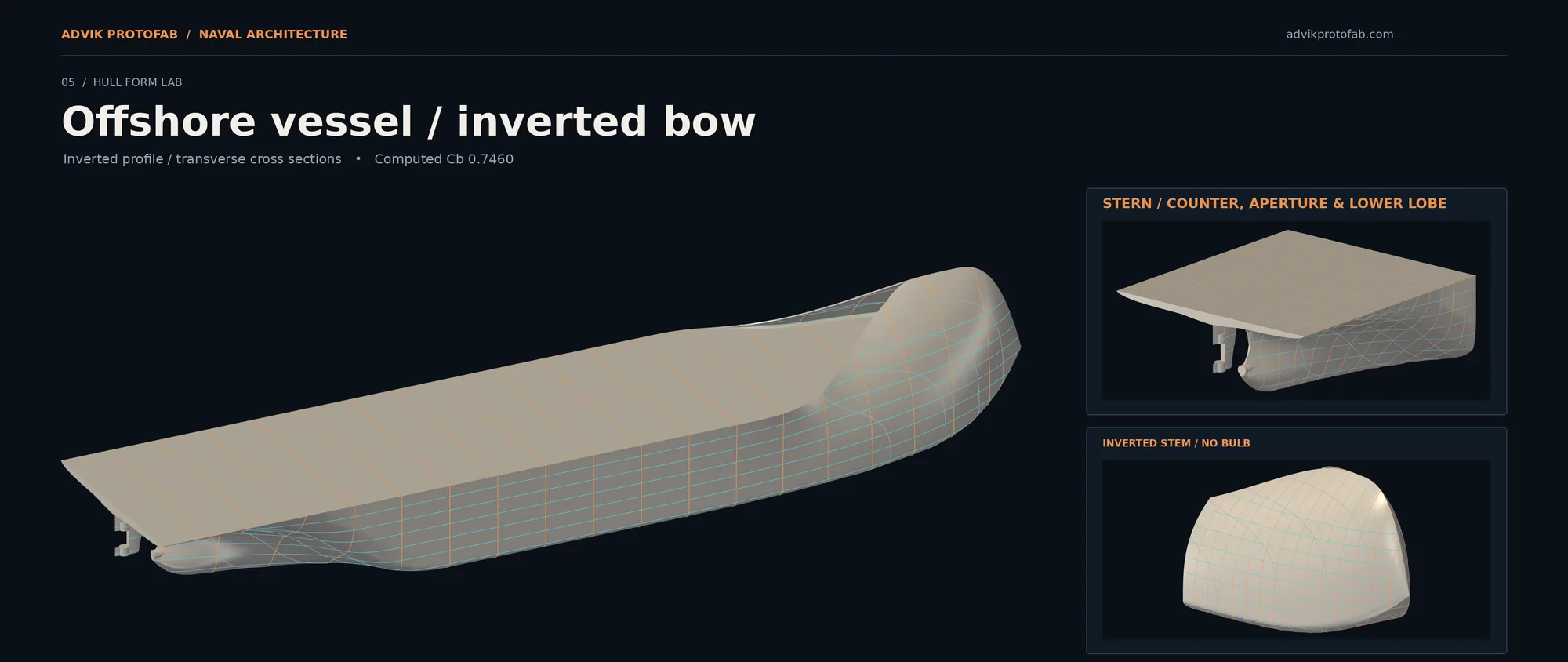
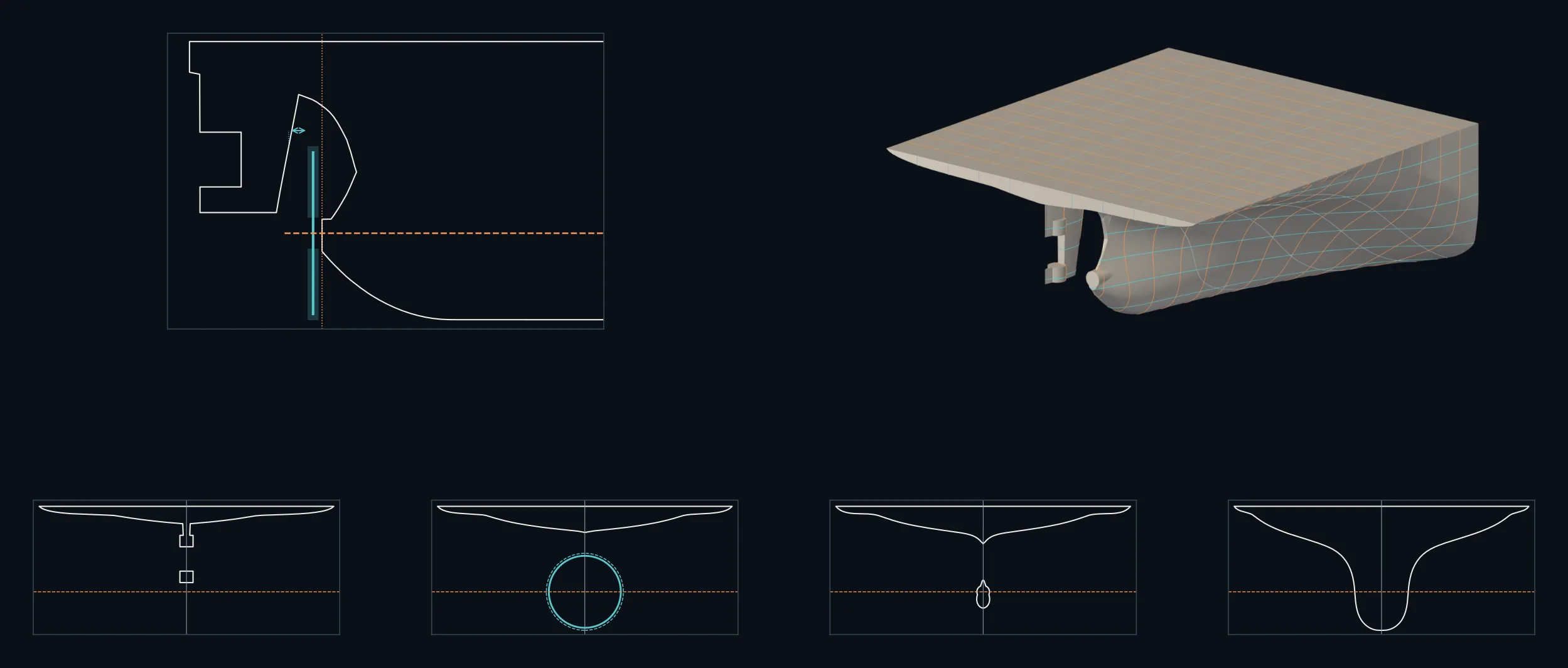
The hulls shown are our own generator's, the flow is our published example. A client's drawings and the model built from them are never shown.
Hull flow · propeller inflow · shaft-line loads
Every unevenness in that wake returns to the shaft line as fluctuating thrust, torque and bending moment at the propeller boss. We compute the viscous flow around the hull, sample the wake where the propeller turns, and carry it through the blade to the loads the shafting and its bearings must carry. The resistance is taken from four systematically refined grids and is reported with the uncertainty the grid itself contributes.
01 · Hull
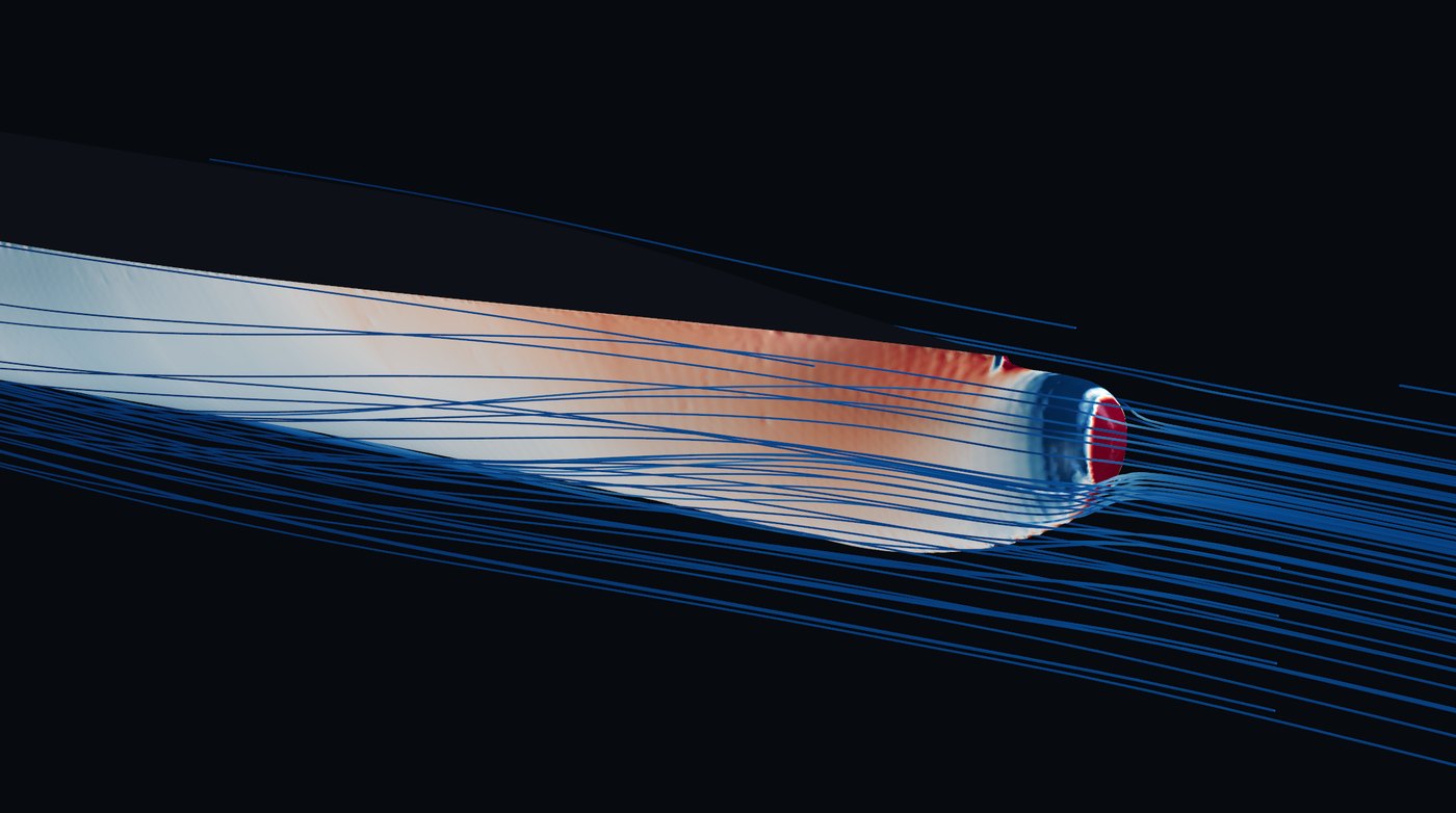
Pressure and skin friction are resolved over the whole hull, so resistance is reported as its friction and pressure parts, and the boundary layer is followed aft to the propeller. The friction share moves by one point across a fivefold change in cell count, which is how it is known to belong to the hull and not to the mesh.
88 % of the model's resistance is skin friction
02 · Propeller plane
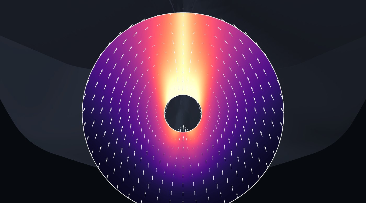
Axial, radial and tangential velocity are sampled at 720 points over the disc. The bright band is the slow water behind the stern; the arrows are the cross-flow each blade meets.
0.33 area-mean nominal wake fraction, on the finest grid
03 · Blade
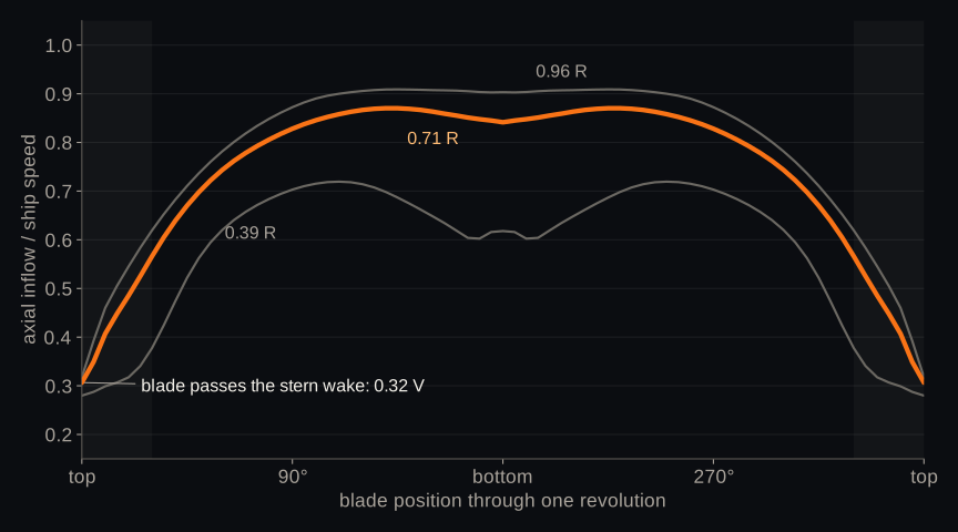
At 0.7 of the radius the inflow falls from 0.85 to 0.32 of ship speed as the blade passes under the stern. That swing marks the sector to investigate for blade loading, cavitation and fatigue.
0.54 V swing in inflow, every revolution
04 · Shaft line
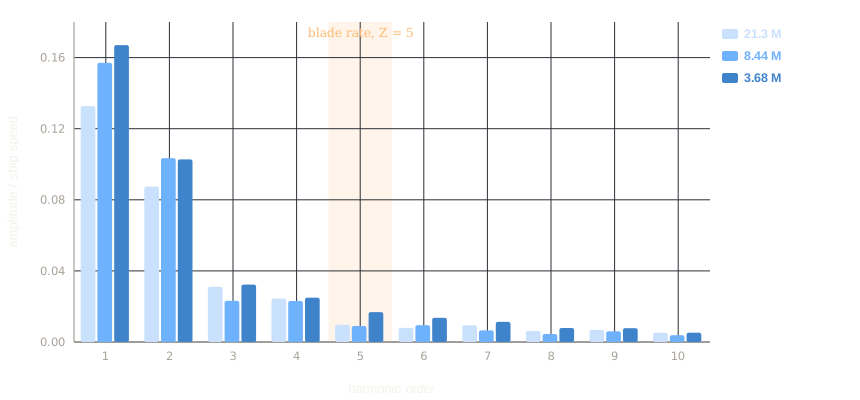
The spectrum is the disc-mean amplitude on the three finest grids, and the colours in the figure are those grids. It is still moving with refinement, so it shows which orders dominate, not a force to design to. The marks beside the list are the shaft load each family of orders can produce.
Method. Steady RANS, k-ω SST, OpenFOAM. The mesh is refined at the stern with prism layers on the hull. Four grids are built from one specification with every length scaled together, and the resistance is assessed by the ASME V&V 20 grid-convergence procedure. Wake sampling, harmonic analysis and the link to the shaft-line model are done in in-house software.
About this example. A model-scale, double-body calculation of the bare hull, giving the nominal wake without a working propeller. It is shown to demonstrate the method.
Reported as obtained. On this grid family the resistance is converged, to 0.22% at an observed order of accuracy of 2.93. Three meshes, stopping at 8.4 million cells, would have returned an order of 0.83 and a grid uncertainty of 3.18%. The wake quantities are not converged. The area-mean wake fraction reads 0.30, 0.32 and 0.33 on the three finest grids, still rising, and is quoted from the finest. The blade-inflow swing at 0.7 of the radius is steadier, at 0.61, 0.55 and 0.54 of ship speed. A study for a particular vessel is run at its own conditions, with the disc sampled often enough to converge the wake as well as the resistance.
Services
Propulsion shafting is the specialisation. The three supporting capabilities grow from the same engineering, connect to the shaft line where it is affected, and are also taken up on their own. All are carried out on the same basis: clear boundaries for the calculation, stated assumptions, and results another engineer can repeat.
Lead practice
The complete shaft line, from main engine to propeller, analysed on one model. The study is used to set chock heights, to decide whether the stern tube should be slope bored, to establish which bearing reaches its limit first, and to explain a vibration or bearing-temperature complaint.
The basis of the analysisSupporting capability
Design, integration and upgrading of shipboard auxiliary machinery (pumps, heat exchangers, refrigeration plant, compressors, generators) and the piping that serves it, including the stern tube lubrication and cooling services and the seating and thermal effects that reach the shaft line.
Scope of the design workSupporting capability
Calculation or design directed at one machine or one defined engineering question: verification, uprating, damage investigation or replacement selection, including couplings, thrust arrangements, stern gear and seals.
How an engagement is definedSupporting capability
Computational tools of the kind behind the shaft-line and propeller analyses, built for a client’s own engineering problem: solvers on stated physics, measurement and data systems, and machine learning where it improves on a conventional method.
Try the calculatorsIn-house tool Beta release
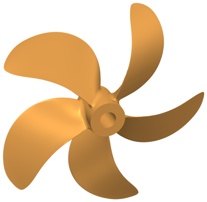
From fixed-pitch propeller particulars to a blade geometry, the offset table and section drawings the manufacturer works from, a solid model, and a three-mesh strength screening with a convergence record. The propeller’s mass and inertia are returned to the shafting calculation, so the propeller and the line are assessed on the same data.
Drag to turn · click, then scroll to zoom · double-click to reset
Why speed matters in design
Ship design converges by iteration: mission, proportions, hull form, arrangements, powering, weights, stability and structure are revisited, each turn on firmer ground. The propeller sits in the powering loop, and every neighbouring decision acts on it.
01
Hull form fixes the wake and the thrust deduction. Resistance and speed fix the thrust. The engine fixes power and revolutions. Draught and the stern arrangement limit the diameter. Cavitation and hull-pressure vibration set the blade area and skew. Change any one of them and the best diameter, pitch ratio, blade number and area ratio move with it.
02
When a three-dimensional propeller costs a day of CAD work it is built once and carried unchanged through the later turns, and the assumptions behind it go unchecked. At under a second it is regenerated at every turn. A sweep of fifty variants of diameter, pitch and blade number costs about forty seconds of computing time, so the designer can look at the alternatives and not only at the first estimate.
03
Concept: envelope, mass and polar inertia for the weights estimate and the shafting. Preliminary: geometry for panel-method and CFD work. Contract: the basis for the drawing and the manufacturer’s enquiry. Detail: the casting pattern, additive-manufacturing preparation and a strength screening.
04
Rebuilt from its particulars, the propeller shows where it absorbs the engine’s power, how far that point lies from the efficiency optimum, and what margin its blade area leaves against cavitation. Set beside trial data corrected to ISO 15016 it shows whether propeller and engine were matched at delivery, and ISO 19030 indicators then track what hull and propeller have lost since. The result informs a decision on re-pitching, on replacement at the next dry-docking, or on accepting an engine rating.
These are screening studies, on Wageningen B-series open-water characteristics unless the propeller’s own curve is available. They give the engineering decision a sound basis, and where model tests or class approval follow, we take the study through them with you.
Technical evidence
Each panel opens the calculation behind a claim above: the reference shaft line and its analysis sequence, and four example propellers reported as obtained, including one that exceeds its allowable and one still under mesh refinement. The hull-flow example above reports viscous resistance to a grid uncertainty of 0.22% on four meshes, and states the wake quantities that have not yet converged.
Reference calculation
Every figure below is output from the in-house shaft-line software applied to a single reference vessel; none is an illustration of a generic arrangement. The shafting is 39.2 m overall, with a six-cylinder two-stroke engine directly coupled to a five-bladed propeller and rated 18 660 kW at 91 r/min.
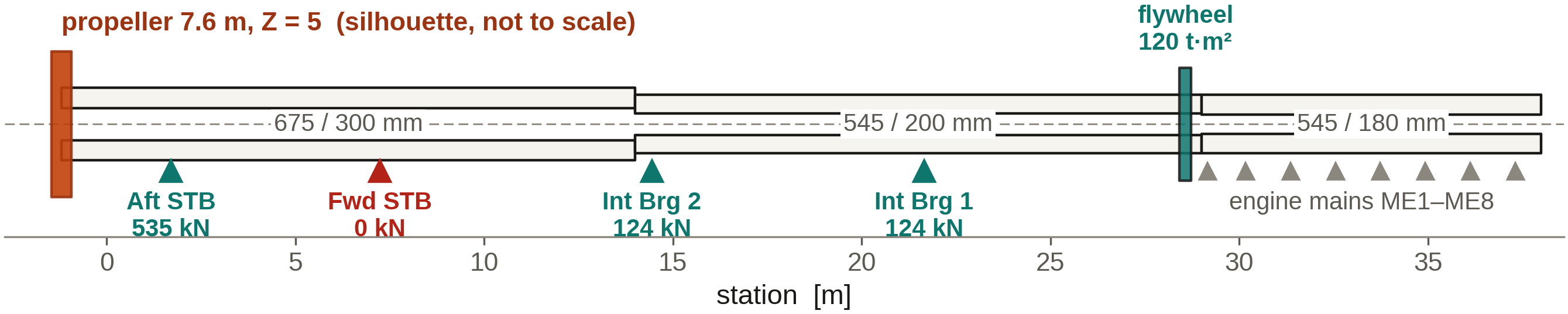
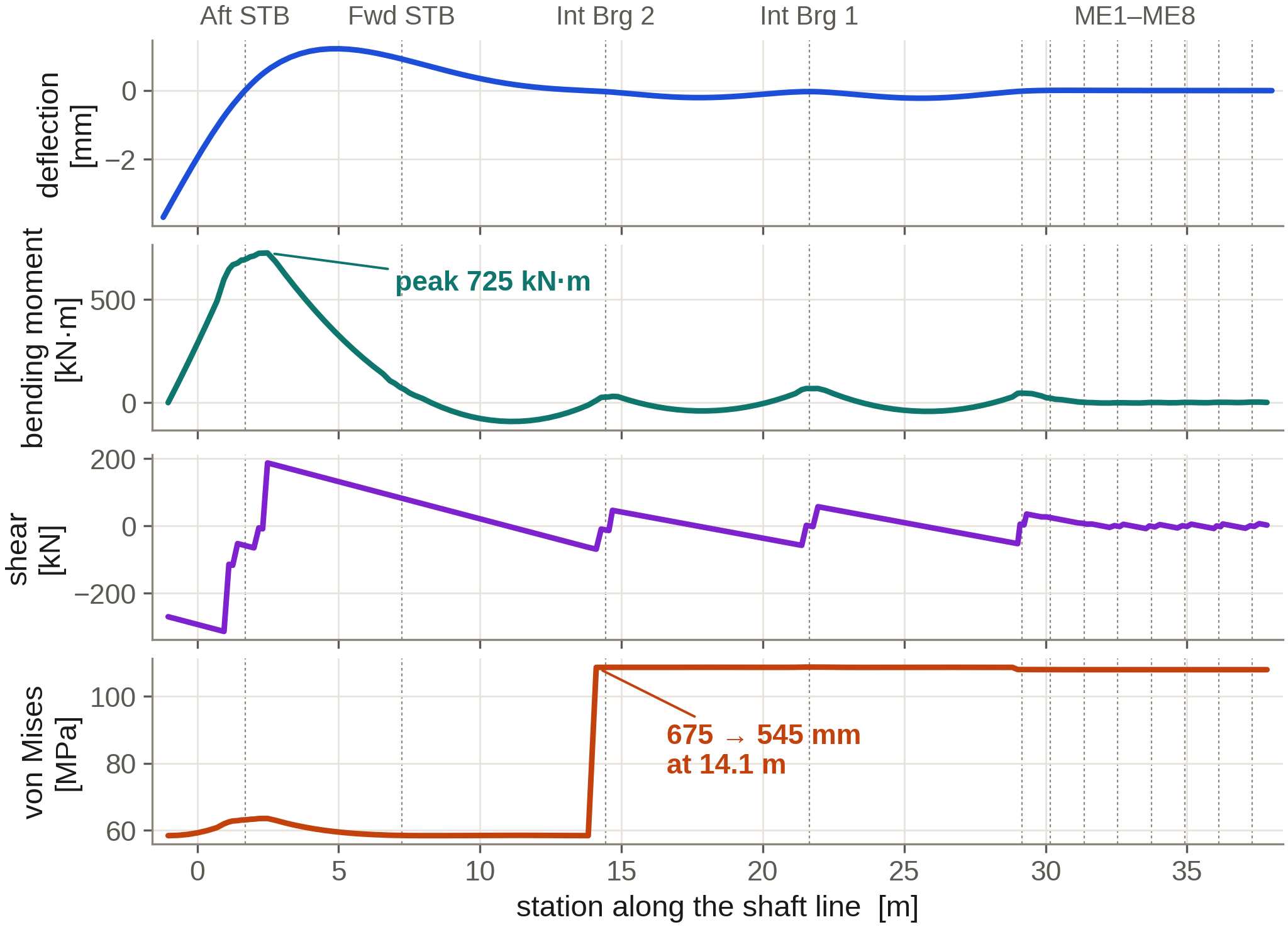
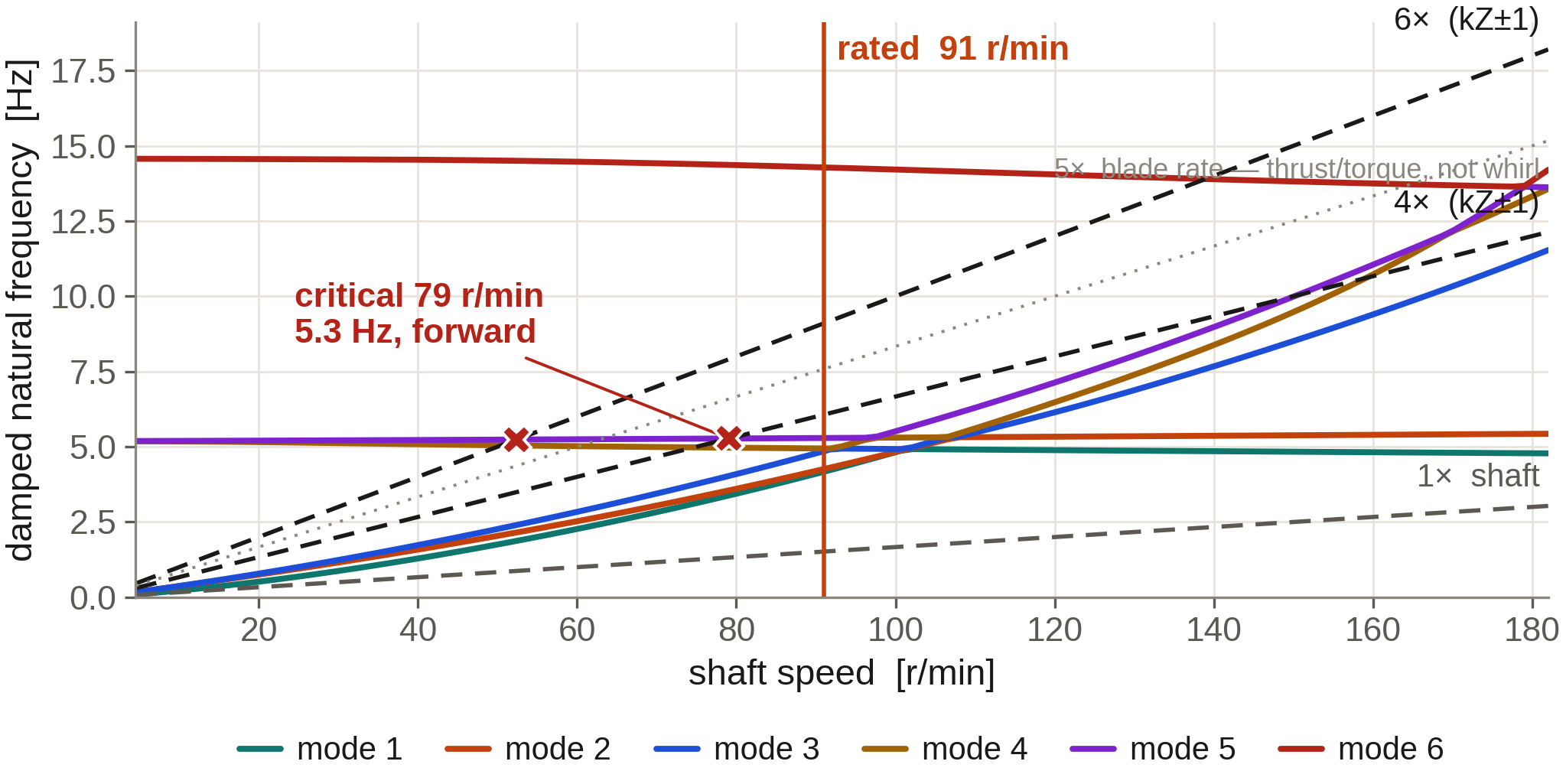
Three further figures are shown on the shafting page: the stern tube pressure field, the support influence coefficients, and the projected bearing wear. An absolute wear life is quoted only where a dry-dock wear-down measurement is available to calibrate the rate.
Sequence of the analysis
01
Bearing reactions, slopes and lift-off loads, the influence of each adjustable support, and the hull deflection cases supplied for the vessel.
02
The journal film at the load and misalignment produced by the alignment: pressure distribution, minimum film thickness and the load share carried by asperity contact.
03
Torsional, axial and lateral response of the same rotor. Dynamic bearing loads and shaft orbits are returned to the lubrication model where the duty requires it.
04
Relative duty of each bearing, and the effect of slope boring the stern tube on that ranking. Absolute wear life is quoted only against a measured wear rate.
An alignment calculation is complete when the free body, the beam model and the acceptance criteria can each be reconstructed from the report.
A study issued by Advik Protofab is an engineering calculation prepared for the yard, the owner and the superintendent, and we stay with it until it has served its purpose. The party a classification society recognises for the vessel makes the submission, with a report written so that it can be presented and defended, and we support it through the review: we answer the society’s or the flag administration’s questions on our work and run any further cases they ask for, until those questions are closed. Where a result depends on a measurement that has not been taken, such as a jacking curve, a wear-down record or a hull deflection survey, the report states the dependency and its effect rather than assuming a value.
Why it matters
Modelling a blade, preparing it for analysis and proving the mesh are the steps that consume the most skilled time. Here they run as one procedure, so a change of particulars is a re-run and not a new task.
01 · Process automation
Geometry, solid model, mesh, solution and report follow one another without re-keying. Mesh volume is checked against the solid and force equilibrium is verified on every run. Every input and result file is kept, so the work can be audited or repeated.
02 · Rapid prototyping
Blade number, diameter, pitch, area ratio and skew can be varied and each variant returned with its mass, inertia and root stress. Alternatives are compared on evidence before a pattern is cut or a build is started.
03 · Engineering candour
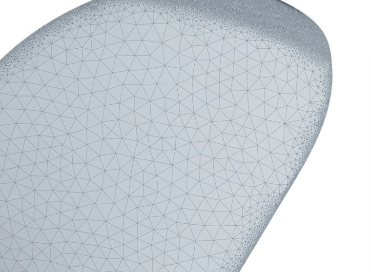
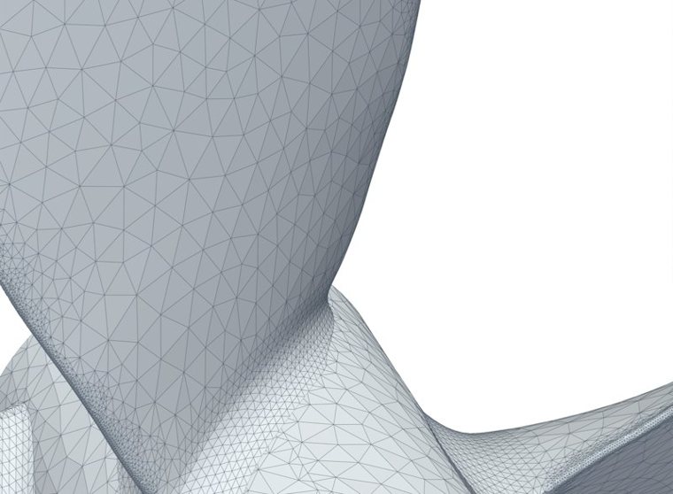
Each study is solved on three meshes, and the screening result is issued once the peak stress has converged; until then the mesh is refined further. Where a design exceeds the allowable the report says so plainly. Both cases appear among the four examples below.
Four examples
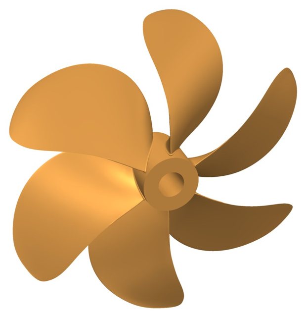
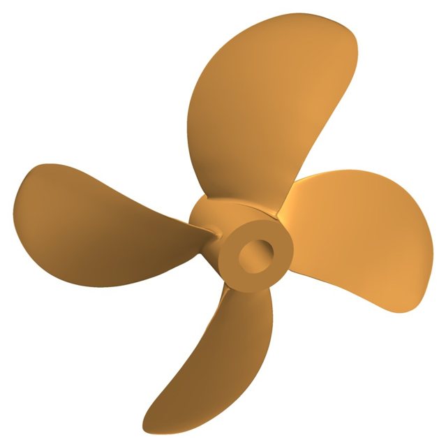
Illustrative designs produced from stated particulars, in cast nickel-aluminium bronze, grade CU3. The screening allowable is 65.6 MPa, the specified minimum tensile strength divided by 9.
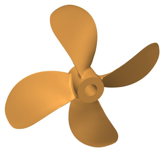
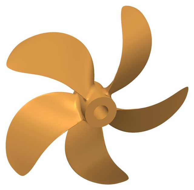
Manufacturing route
Traditional casting
Additive manufacturing
This is a beta release, offered for evaluation and pilot studies. Results are a linear-elastic static screening, the step before classification-society approval, and we support the design through that approval, answering the society’s questions on our work. Analyses beyond those illustrated, including fatigue, hydrodynamic pressure loading, other materials and foundry allowances, are undertaken on request, each with its own timeline. Advik Protofab charges for engineering services only; no software is sold or licensed.
Commissioning a study
Scope, input data, assumptions and acceptance criteria are agreed before calculation begins. A non-disclosure agreement can be executed before any drawing is exchanged.
01
The vessel, the machinery concerned and the decision the study has to support. An initial technical response within two working days.
02
The drawings, records and measurements available, and a written list of what is missing with the effect of each gap on the result.
03
Conditions, standards applied, acceptance criteria, deliverables, schedule, commercial terms and exclusions, agreed in writing.
04
One confirmed model, results reported in the terms of the original question, and a technical review with your engineers at close-out.
You supply
Drawings can follow the first reply. Missing data is listed with its effect on the result, not replaced with an undeclared assumption.
You receive
It decides
Every stage, and what it requires and produces, is set out on the engagement page.
Work with us
The question may concern the hull and the flow it delivers to the propeller, the propeller itself, the propulsion shaft line, or the machinery and piping systems that serve the ship. Tell us what the vessel or the machinery is doing, what information is available and what decision has to be made. We will define the scope and the information required.
Enquire directly about a naval architecture or hull-flow study, a shafting study, a propeller pilot study, a machinery or piping design, a customised analysis or a software development.