
Services · Propulsion shafting · Propeller geometry and offsets
Propeller geometry and offsets for the manufacturer
From the particulars of a fixed-pitch propeller to the documents a foundry and machine shop work from: the blade geometry, the offset table at every radius, section and outline drawings, and a solid model of blades and boss together. Each design is screened for blade strength and handed to the shafting calculations with its mass, polar inertia and centre of gravity. The service is in beta release and taken on as a pilot study.
What is produced
- Blade geometry from the particulars: diameter, number of blades, pitch distribution, blade area, skew and rake, generated in under one second.
- Sections from published thickness forms and mean lines, laid off normal to the mean line as their definitions require, with the root fillet added.
- The offset table and section drawings at every radius, with the expanded outline and the issuer block on every sheet.
- A solid model of the blades and boss, with the taper bore, for the pattern maker and for strength analysis.
- Strength screening by finite elements on three successive meshes, with the change between meshes reported so the converged stress can be judged.
- Mass, polar inertia and centre of gravity, integrated from the sections and passed to the alignment and torsional calculations.
How the geometry is checked
The parametric model has been tested against four manufactured propellers with known drawings and stamped weights, and written up as report APPL-PGV-01. Built from a complete drawing, the reference propeller's mass comes within 0.22 % of the stamped weight and its expanded area within 0.06 % of the stated area. An independent propeller, none of whose blade data entered the model, generated from its particulars sheet alone, comes within 2.0 % of its stamped weight.
The report also measures what a parametric model cannot know in advance: makers design blade thickness 2 to 13 % above the classification minimum, varying by maker and radius. Where a design must match an existing propeller closely, its drawing is used in place of the rule.
Examples
Four propellers from stated particulars
Illustrative designs in cast nickel-aluminium bronze, screened against an allowable stress of 65.6 MPa. They show the range the generator covers and the form the results take; a client design is produced from that vessel's own particulars.
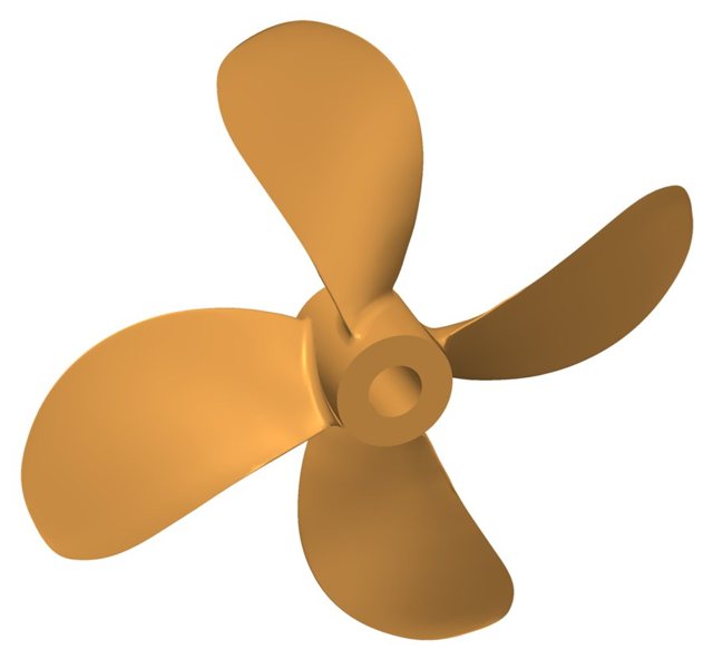
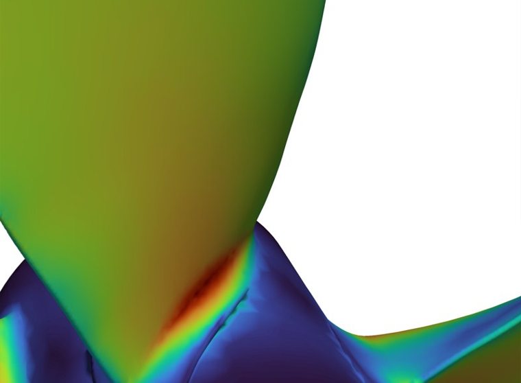
All four examples, the interactive model and the manufacturing route
Deliverables
What you receive
- The offset table and section drawings, ready for the manufacturer.
- The expanded and projected outlines and the pitch, skew and rake distributions.
- The solid model in a neutral CAD format.
- The strength screening with its mesh study.
- Mass, inertia and centre of gravity, and their effect on the alignment and the torsional critical speeds.
Scope of the beta
What the pilot covers
The beta covers fixed-pitch propellers from their particulars or from an existing drawing. The strength result is a screening for the design stage; the classification society's own approval of the final design follows its rules, and the documents are prepared to support it. Open-water performance is set against the Wageningen B-series at the screening stage, and the match to the engine is made as a propeller and engine matching study.
Questions from owners and yards
Frequently asked
Can you reproduce an existing propeller from its drawing?
Yes. The drawing's own section data, outline and boss are used, and the result is checked against the drawing's stated mass and area. This is how a replacement or spare is prepared when the original maker's model is held elsewhere.
Which section forms are used?
Published forms with tabulated ordinates, such as the NACA 66 thickness form with the NACA a = 0.8 mean line, reproduced to the last printed digit. The form is stated on every drawing, so the manufacturer and class know exactly what is being made.
Is the strength result a class approval?
It is a design-stage screening, made on a solid model with a converged mesh and stated loads. It shows early whether the blade thickness is adequate, and the final design is then submitted for the classification society's approval with the documents it needs.
How does the propeller connect to the shafting work?
Its mass, polar inertia, centre of gravity and entrained water go directly into the alignment and torsional calculations of the same vessel case, so the effect of a new propeller on the bearing loads and the barred speed range is known before it is cast.
Commissioning
Start with the drawings you hold
Send the propeller particulars or the existing drawing, with the engine rating and the vessel's service condition. An initial technical response follows within two working days, then a written scope and proposal for the pilot study: the geometry to be produced, the documents for the manufacturer, the strength screening and the schedule. A non-disclosure agreement can be put in place before any drawing is exchanged.
Related analyses
Shaft alignment analysis
Bearing reactions, slopes, lift-off and influence coefficients for the hot and cold conditions, with chock heights or offsets for installation.
Torsional vibration analysis
Natural frequencies, order crossings, shaft stress against class limits and barred speed ranges, on a mass-elastic model of the complete train.
Axial and whirling vibration
Axial modes against blade-rate excitation and lateral whirling with bearing coefficients from the film solution, in one rotor model.
Stern tube bearing analysis
Film thickness, edge loading, lift-off speed and comparative wear for water- and oil-lubricated stern tube bearings, straight or slope bored.
Propeller and engine matching
Where the propeller absorbs the engine power across the operating range, with light-running, fouling and weather margins set out.
3D hull, CFD and wake
The hull rebuilt from your drawings, with viscous resistance and the wake the propeller works in.