
Services · Propulsion shafting · Stern tube bearing analysis
Stern tube bearing analysis
An analysis of the lubricating film in the stern tube bearings at the load and the shaft slope the alignment produces. It shows whether the bearing runs on a full film or rubs, at what speed the shaft lifts off, where along the bush the load is carried, and how a straight bore compares with a slope-bored one. It covers water-lubricated polymer bearings and oil-lubricated white metal, for a newbuilding, a bearing replacement, or a vessel with high temperature or rapid wear-down.
What the analysis covers
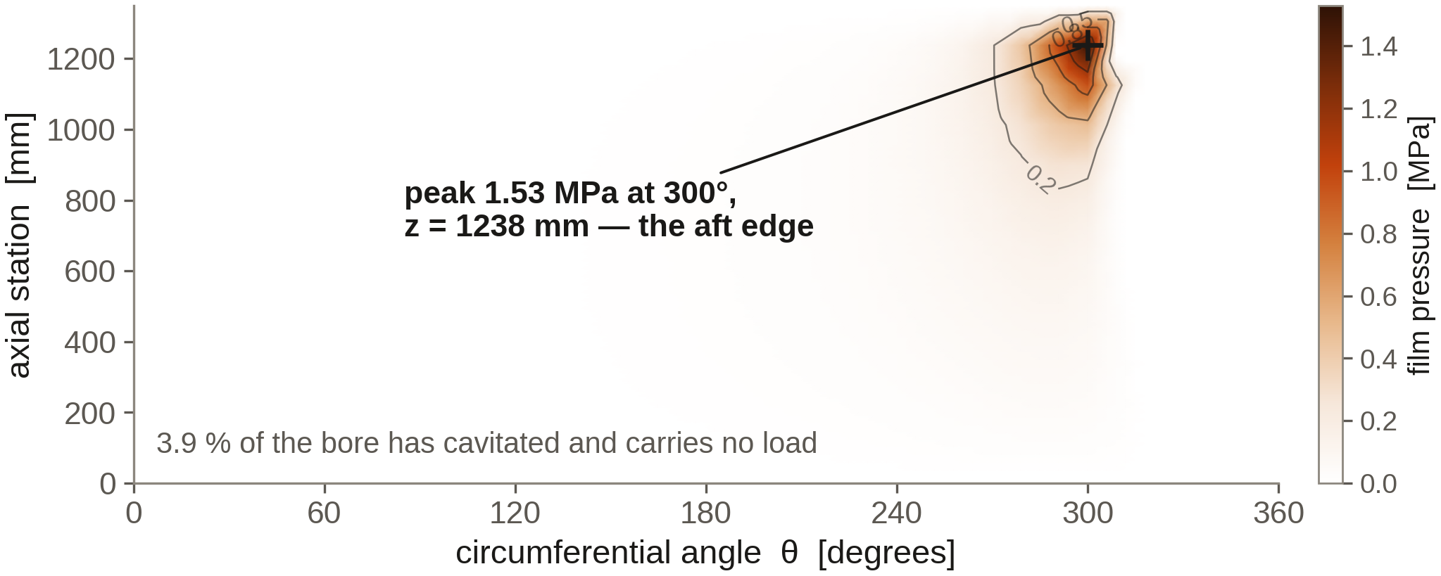
- The film at the alignment load and slope. Pressure distribution, minimum film thickness and its position along the bush, solved over the full bearing length so that misalignment is felt where it acts.
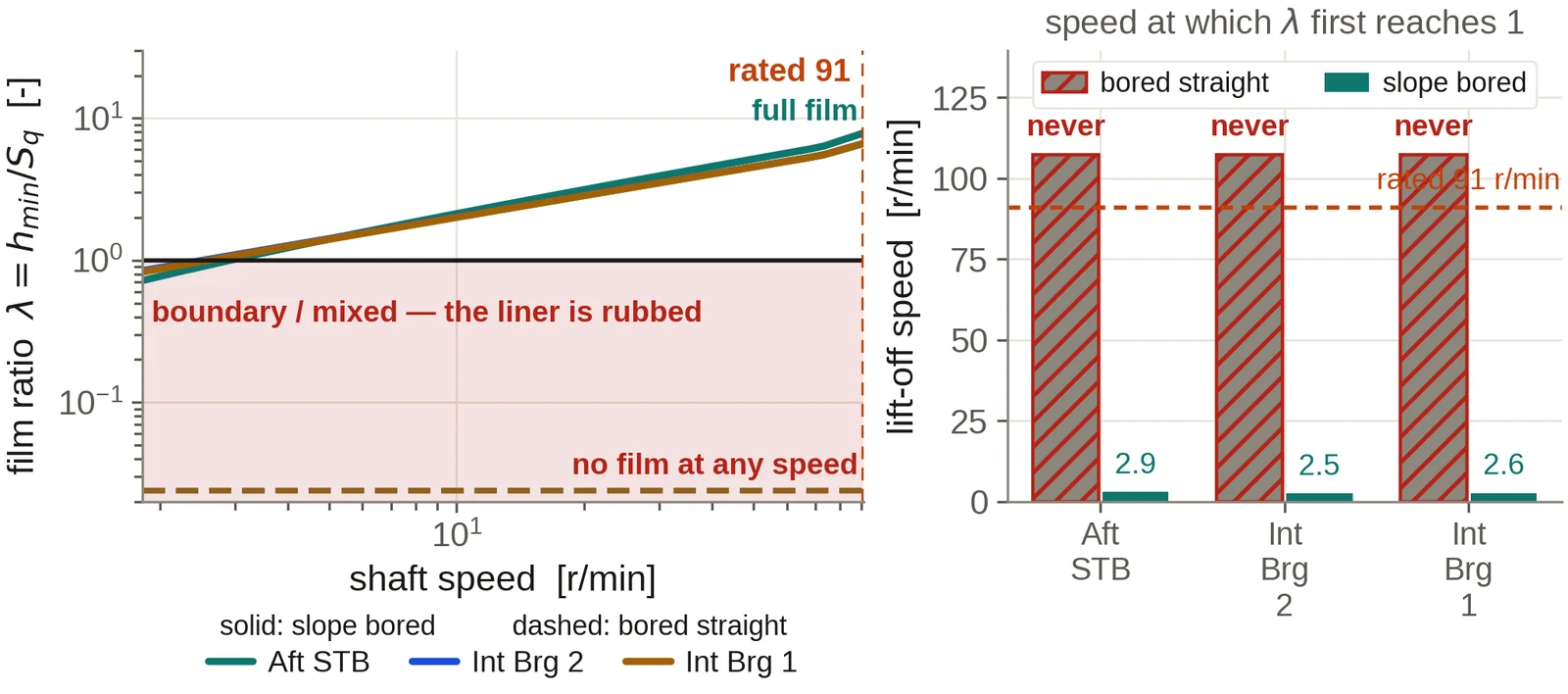
- The lubrication regime. The ratio of film thickness to surface roughness, which separates full-film running from mixed lubrication where the liner is rubbed.
- Lift-off speed. The shaft speed at which the film first separates the surfaces, for the straight and the slope-bored bush.
- Thermal check. The friction power, the temperature rise in the film and the margin to the liner material's temperature limit.
- Bearing duty and material choice. Pressure and sliding speed against the limits of the candidate bearing grades.
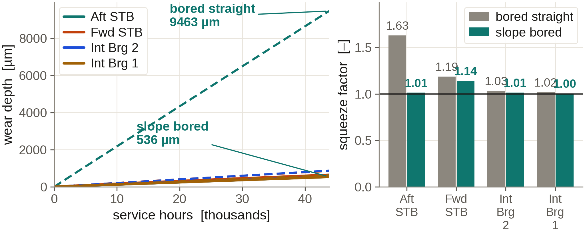
- Comparative wear. A ranking of the bearings and of the bore options by wear duty, calibrated to wear-down records where they exist.
Why the alignment and the bearing are solved together
A stern tube bearing designed to an average pressure can still fail at its aft edge. The propeller overhang tilts the shaft inside the bush, and the relative slope, measured in tenths of a milliradian, decides whether the film spreads along the bearing or collapses at one end. That slope comes from the alignment, and the alignment depends in turn on where along the bush the bearing reaction acts.
The in-house shaft-line software passes the load and slope at each bearing from the alignment to the film model once, from the same vessel case, and returns the film's stiffness and damping to the vibration model. The bearing is never analysed with a load or slope copied from another calculation.
Water-lubricated stern tubes are reported with the film Reynolds number at the operating point, because a seawater film in a large bearing need not remain laminar, and the result is stated with that in view.
Worked example
Straight bore against slope bore on the reference line
The reference installation's aft stern tube bearing: a 675 mm journal, 1 350 mm long, water lubricated, turning at 91 r/min under about 375 kN.
Deliverables
What you receive
- Film pressure, thickness and regime for each bearing and condition.
- Lift-off speed and the minimum speed for continuous running on a full film.
- A recommendation on slope boring, with the slope to bore to.
- Bearing duty against the candidate materials, and the temperature margin.
- A wear ranking, and the life estimate once wear-down data is available.
Input data
What the study needs
- The stern tube arrangement drawing with bush lengths, bore and clearance.
- The bearing material and lubricant: seawater, freshwater circulation or oil.
- The alignment calculation, or the data to make one.
- Wear-down records, poker gauge readings and bearing temperature logs, which turn the wear ranking into a life estimate.
Questions from owners and yards
Frequently asked
Should our new stern tube bearing be slope bored?
The study answers this directly. It calculates the shaft slope in the bush for the governing conditions and compares the film and the edge pressure for a straight and a slope-bored bush. Where slope boring is advised, the slope and the bore geometry are given for the machine shop.
We are converting from oil to water lubrication. What changes?
A seawater film is far thinner than an oil film at the same load and speed, so the margin against edge loading is smaller and the lift-off speed is higher. The study recalculates the film for the new material and lubricant at the same alignment, and states whether the alignment or the bore should change with it.
Our aft bearing wears faster than expected. Where do you start?
With the wear-down history, the bearing temperatures and the loading conditions the vessel works in. These are set against the film calculated at the alignment, which usually shows whether the cause is edge loading, low-speed running below lift-off, abrasive water, or a combination, and what will correct it.
Do you work with specific bearing manufacturers' materials?
Yes. The bearing duty is checked against the published pressure, speed and temperature limits of the grades under consideration, so the choice of material can be made on the calculated duty.
Commissioning
Start with the drawings you hold
Send the shafting arrangement drawing and whatever machinery data is to hand. An initial technical response follows within two working days, then a written scope and proposal: the conditions to be calculated, the data still needed, the deliverables, the fee and the schedule. A non-disclosure agreement can be put in place before any drawing is exchanged. The calculation is then carried through to a report a yard, a superintendent or a classification society can follow and reproduce, and questions raised on it are answered by us until the review is closed.
Related analyses
Shaft alignment analysis
Bearing reactions, slopes, lift-off and influence coefficients for the hot and cold conditions, with chock heights or offsets for installation.
Torsional vibration analysis
Natural frequencies, order crossings, shaft stress against class limits and barred speed ranges, on a mass-elastic model of the complete train.
Axial and whirling vibration
Axial modes against blade-rate excitation and lateral whirling with bearing coefficients from the film solution, in one rotor model.
Propeller and engine matching
Where the propeller absorbs the engine power across the operating range, with light-running, fouling and weather margins set out.
Propeller geometry and offsets
Blade geometry, offset tables and section drawings for the manufacturer, with mass and inertia for the shafting calculations.
3D hull, CFD and wake
The hull rebuilt from your drawings, with viscous resistance and the wake the propeller works in.