
Premium service · 3D hull · CFD · wake
A 3D hull for the ship you already operate
Yards rarely hand over the 3D hull model. We rebuild it from the drawings and data you already hold, check it against your own hydrostatics, and use it for viscous CFD: resistance split into friction and pressure, the wake where your propeller turns, and a speed–power curve calibrated to your own trial or model-test data.
Send drawings for a feasibility review No charge until we confirm a good-quality hull can be built.
What owners and managers use it for
- Performance baselineA speed–power reference for your hull at the loading conditions you actually sail, calibrated to sea-trial or model-test results, against which noon-report and sensor data can be read.
- EEXI, EEDI and CII workSupporting analysis for the technical file and for improvement plans: hull resistance, propulsion inputs and the effect of a change, documented so a verifier can follow it. Acceptance stays with your class society or verifier.
- Propeller and energy-saving devicesThe nominal wake at the propeller plane, with its harmonics, as the input a propeller redesign, a duct or a fin study needs. Alternatives are compared on the same mesh and numerics.
- Shaft-line loadsThe wake carried through the blade to the fluctuating thrust, torque and bending at the propeller boss, for the shafting and bearing assessments we already run.
From your drawings to the flow around the hull
-
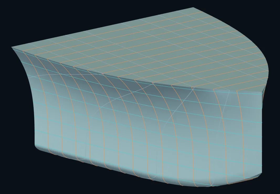
01 · Drawings in
Sections, waterlines and profile, from paper or PDF
Lines plan or body plan, profile, stern frame and rudder drawings, offset tables where they exist. Every curve is registered to the ship's own frames and datum; nothing is filled in from a guess.
-
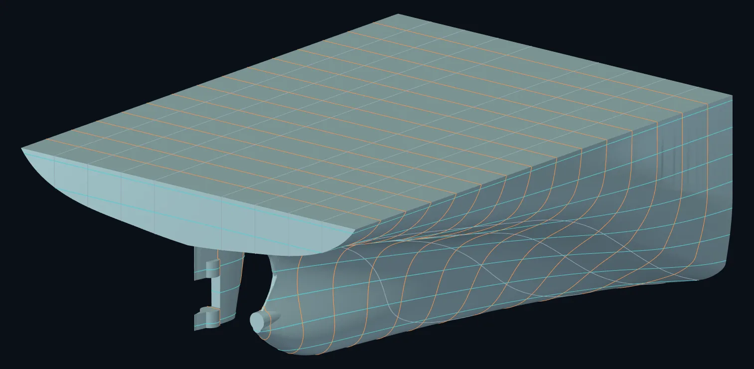
02 · Surface
A closed, faired surface, stern included
Counter, aperture, shaft housing and rudder horn are built, not smoothed over, because that is where the wake is made. The surface is checked closed and watertight, and its displacement, LCB and coefficients are compared with your hydrostatic tables.
-
03 · Viscous CFD
Resistance, split into what causes it
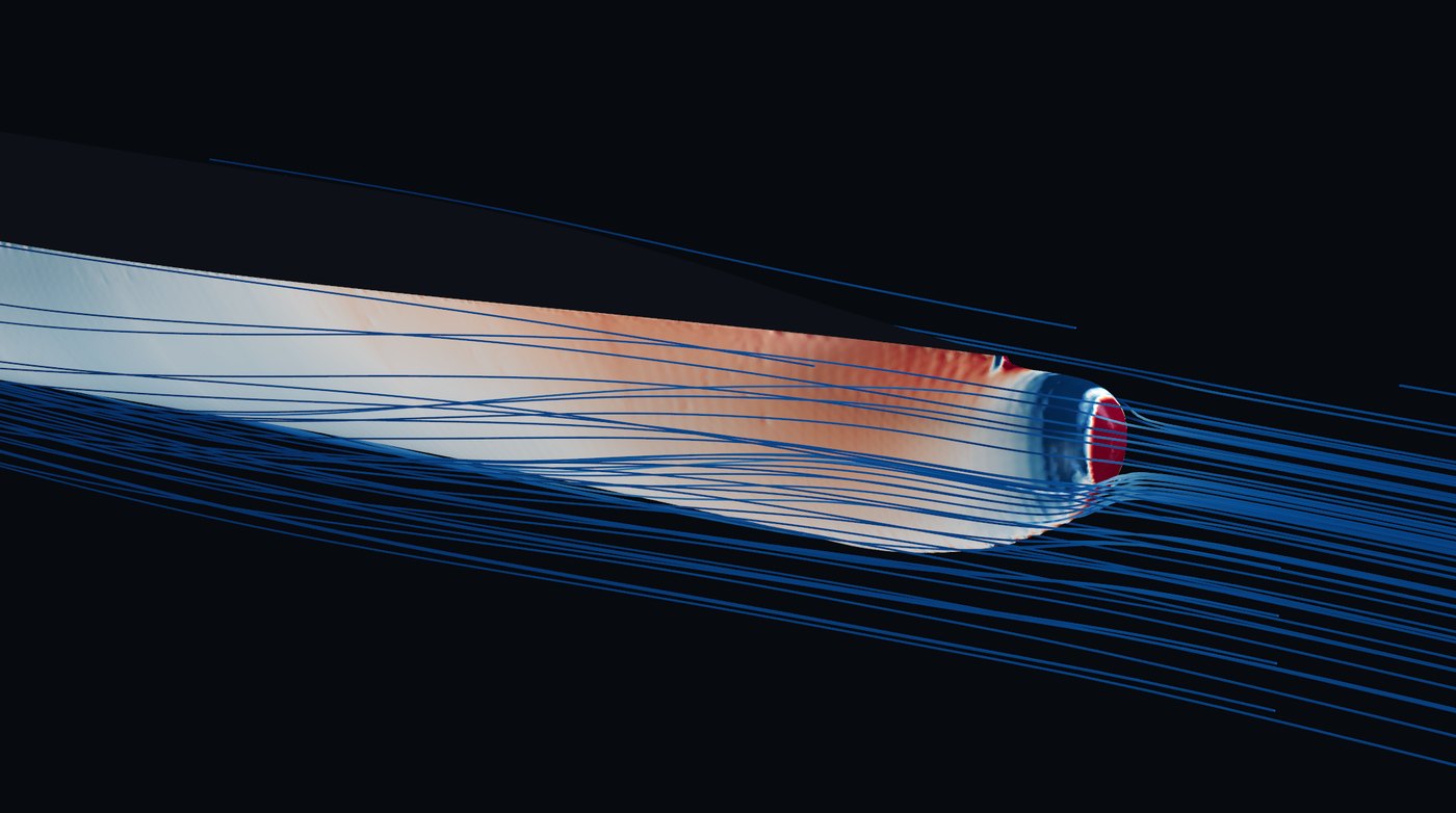
Steady RANS with the k-ω SST model on systematically refined grids, so the effect of the grid on the answer is measured rather than assumed. Friction and pressure resistance are integrated from the hull surface.
0.22%grid uncertainty on resistance, four grids to 21.3 M cells, in our published example
-
04 · Wake
What the propeller actually meets
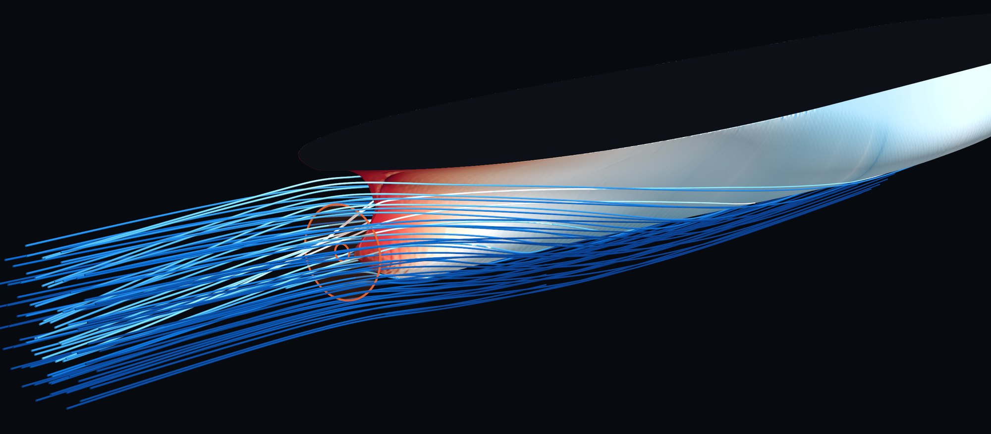
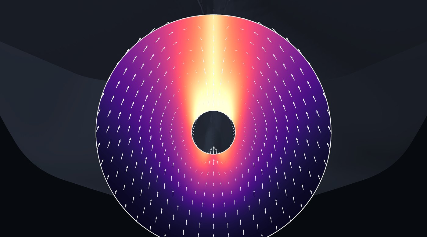
Three velocity components sampled over the propeller disc, reduced to the mean wake, its radial distribution and its harmonics: the quantities a propeller designer and a shafting engineer each need.
720wake samples, 12 harmonic orders resolved
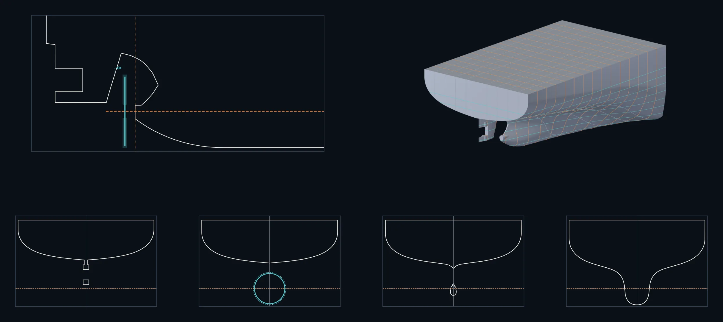
The stern is drawn and checked before any flow is computed
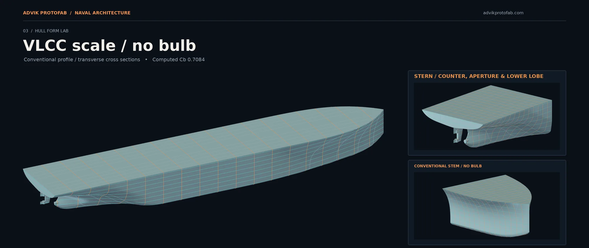
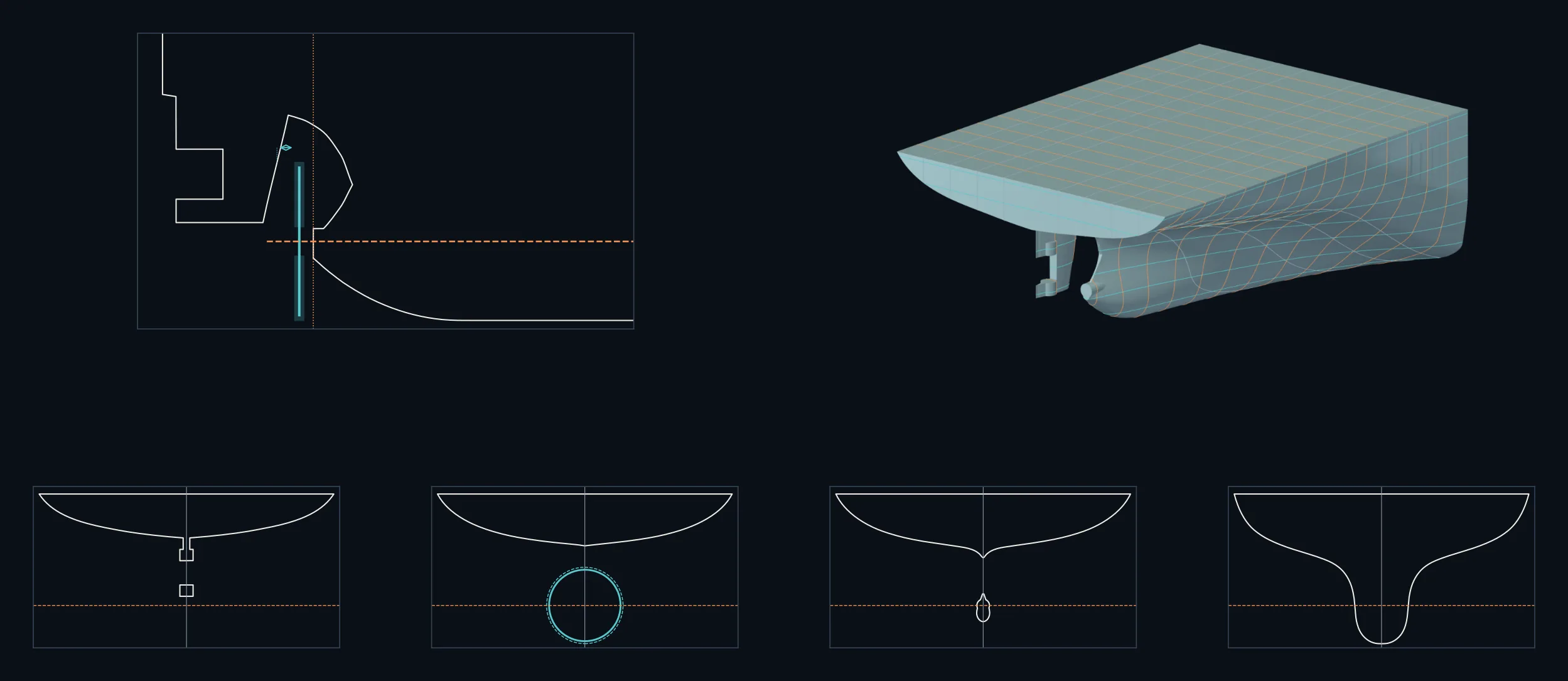
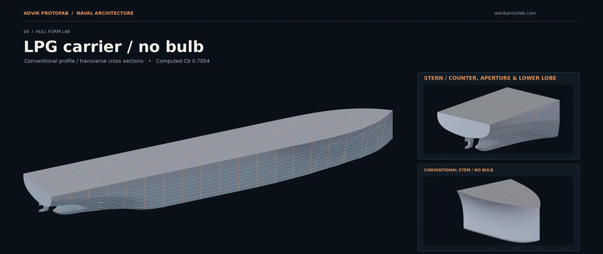
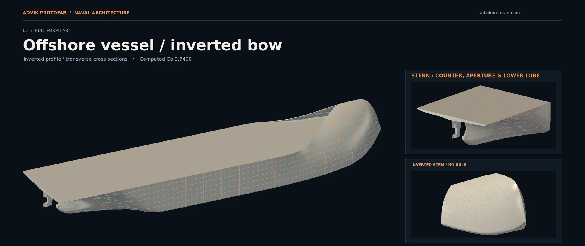
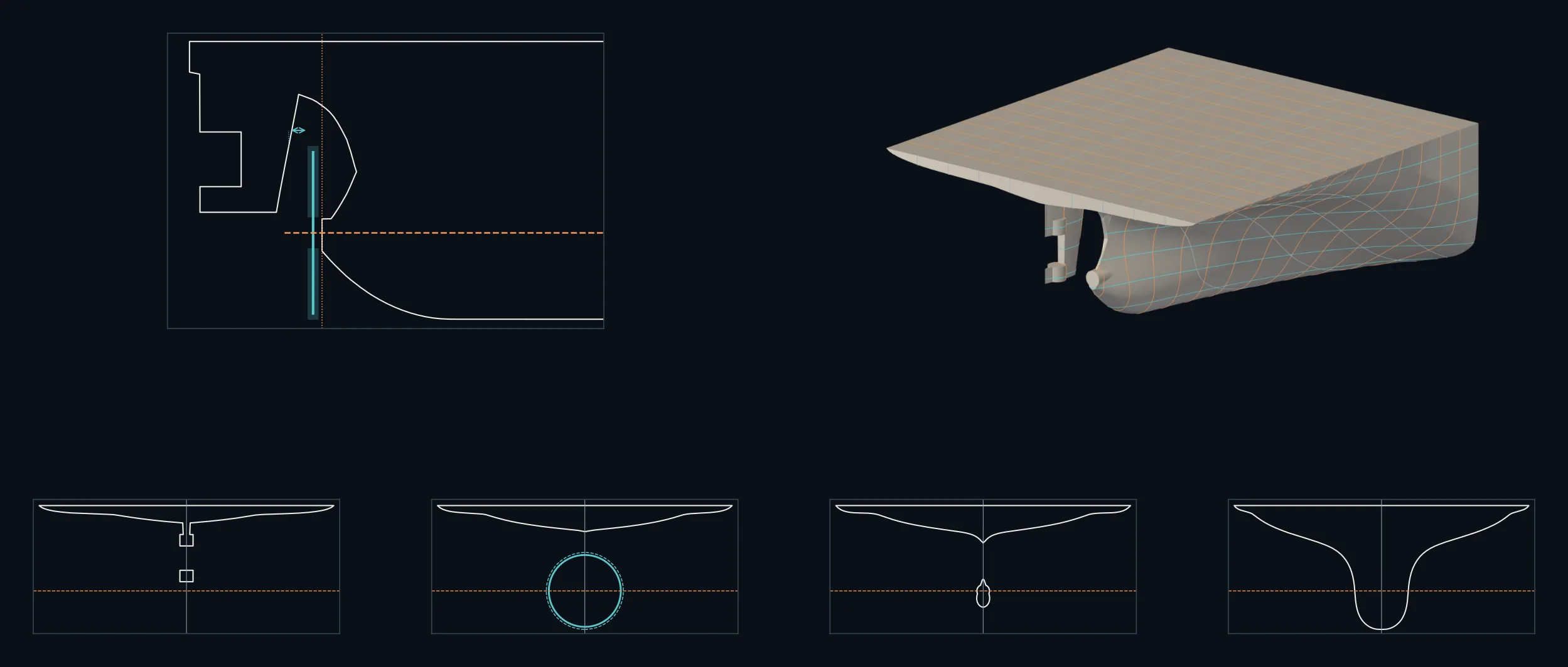
For every hull we draw the stern arrangement: the centreline profile with the shaft line, the propeller disc and the rudder horn, and sections through the counter, the propeller plane and the run. The propeller's clearance to the hull and the horn is checked on the actual surface. These are three of our generator's hulls, shown without their scales; your report carries the dimensioned set.
What you receive
- The 3D hull surface (STL, GLB and VTK formats), closed and watertight, in metres on your ship's datum
- A lines plan of the reconstructed hull and a fit report: how closely it follows each of your drawings
- The stern arrangement with propeller clearances, dimensioned
- Hydrostatics of the 3D hull set beside your hydrostatic tables
- CFD resistance with its friction and pressure parts, and the grid study behind it
- The nominal wake at the propeller plane, with radial distribution and harmonics, as data and figures
- A speed–power curve calibrated to your trial or model-test data, with the method stated
- A report written so another engineer can reproduce every number, and a review meeting
Your drawings stay yours
Documents and the model built from them are used only for your project. Nothing you send appears on this site or in any publication. The pictures on this page are of our own generator's hulls and our published flow example; none carries dimensions or offsets.
A non-disclosure agreement can be signed before anything is sent.
How work is taken on
- 1You send the documents
The list below. Scans are fine if they are legible.
- 2Feasibility review: no charge
We build a trial hull, compare it with your hydrostatics and tell you plainly whether a hull of good quality, and CFD results on it, can be obtained, and if anything is missing, what will close the gap.
Up to 5 working days from a complete set
- 3Quotation and confirmation
A fixed scope, price and schedule. Work starts when the quotation is accepted and the agreed charge is paid.
- 4Hull, CFD and report
Built, checked and reported in the order above, with an interim check of the hull before the CFD starts.
Typically 6 to 8 weeks from payment and complete data
- 5Delivery and review
Files, report and a meeting to go through them. Questions on the report are answered after delivery.
| Stage | Calendar time | Of which computing |
|---|---|---|
| Feasibility review | up to 5 working days | a few hours: trial hull and one coarse flow check |
| 3D hull, fairing, stern arrangement and hydrostatic check | about 2 weeks | under a day |
| CFD grid study at the design condition, four grids | 2 to 3 weeks for a typical package of two draughts and up to five speeds | about a day on 24 cores: the three coarser grids took 7.5 hours in our published example, and the finest, scaled by its cell count, about 12 more |
| Each further draught or speed, on the verified grid | about 5 hours | |
| Report and review meeting | about 1 week | none |
Projects run one at a time on our own 24-core machine, so a start date is given with the quotation. Times assume the documents are complete; a missing drawing pauses the clock rather than being guessed around.
Documents we ask for
Needed
- Lines plan or body plan, with profile and half-breadth views
- General arrangement
- Hydrostatic tables or curves
- Stern frame, rudder and shaft arrangement drawings
- Speed and loading conditions to be studied
Strongly helpful
- Offset table; capacity plan; docking plan
- Model-test report and sea-trial report: these calibrate the speed–power curve
- Propeller drawing
- Noon reports or performance-monitoring data, for calibration in service
The standard study, and what you can add to it
The standard study is where most questions start:
- Steady, model-scale, double-body RANS of the bare hull. Wave-making comes from your trial or model-test data, or from a stated empirical method, and the speed–power curve says which.
- Each result is checked on a family of refined grids. An uncertainty is quoted only where the grids settle. In our published example the resistance settled to 0.22%, while the wake fraction was still rising on the finest grid and is reported as such.
- The wake is the nominal wake, as the propeller designer's input.
If your question needs more, tell us what it is: the rudder, brackets or an energy-saving device in the flow, a working propeller, the free surface, full-scale flow, or further speeds, draughts and trims. The feasibility review shows how each is done with your documents and what it adds to the time, and the quotation covers exactly that scope.
We stay with the work until your objective is met. When the results go to a classification society, a flag administration or an EEXI or EEDI verifier, we answer their questions on the analysis and run any further cases they ask for.
Send the drawings and your question; we will tell you what they can support.
Advik Protofab Private Limited
Marine engineering and naval architecture: hull flow and wake, propeller design, propulsion shafting with the main engine, bearings and propeller assessed as one system, and machinery and piping systems.
1-77, Ganesh Nagar, Chinamushidiwada, Pendurthy, Visakhapatnam 531173, Andhra Pradesh, India
[email protected] · advikprotofab.com